

- Fluoroscopy for Minimally Invasive Spinal and Trigeminal ProceduresSanjeeva Gupta, Ganesan Baranidharan, Manohar Sharma, Harun Gupta
- Understanding of Radiological AnatomyKenneth Lupton, James Baren, Harun Gupta
- Understanding Common Image-guided ProceduresKenneth Lupton, Jamen Baren, Harun Gupta
- Understanding the Pathology of Common Conditions through Magnetic Resonance Imaging for the Pain PhysicianHarun Gupta, James Baren, Kenneth Lupton
- Radiation ProtectionSatish Kamath, Dwarkadas K Baheti
- Informed Consent for Interventional Pain Management ProceduresDwarkadas K Baheti
- Protocol for Interventional Pain Management ProceduresDwarkadas K Baheti
- Role of Investigations for Interventional Pain Treatment ProceduresDwarkadas K Baheti
- Medications Used for Interventional Pain ProceduresKritika Doshi, RP Gehdoo
INTRODUCTION: BASIC PRINCIPLES
- Understanding neuroanatomy of the different structures that can cause spinal pain is essential before attempting interventions.
- We can only see bony structures on fluoroscopy (X-ray) and have to construct a 3D image in our mind and consider the different structures in relation to the bone.
- Bony anatomy and the surrounding structures may not be the same in every patient, especially if they have significant spondylosis, osteophytes, spondylolisthesis, scoliosis, etc.
- Bones are our FRIEND and our EYES. Try to contact the bone before navigating the needle deeper as this will increase safety.
- If you are a beginner, always start with simple lumbar spine interventions and then consider cervical and thoracic followed by trigeminal interventions.
- If you are having difficulty in identifying the target point (TP), look at the TPs one level above and below as this can help identify the TP. In some patients, changing the position can help identify the TP, e.g., lateral to prone position for cervical interventions in patients with short neck.
- Use a standardized terminology to identify the structures for the procedure being done.
- Neural axis safe iodinated contrast should be used where necessary (e.g. epidural, transforaminal injections, etc.).
- Get the level correct:
- Lumbar level:
- Count levels from T12 downward. Be aware of transitional vertebra at the L5/S1 level.
- When performing transforaminal epidural injection, compare the sagittal MRI image with the lateral fluoroscopic view to confirm that the procedure is being performed at the correct level.
- Cervical level:
- Count levels from C2 (largest spinous process) downward and/or
- C7 upward [C7 transverse process (TP) slanting down and T1 TP slanting up]
PATIENT POSITIONS FOR PROCEDURES
- Prone position:
- All lumbar, sacral, and thoracic procedures
- Cervical epidural, lower cervical medial branch block (MBB)/RFD
- Supine position:
- Cervical MBB and radiofrequency denervation (RFD)
- Cervical nerve root block
- Cervical disc procedures
- Lateral position:
- Cervical MBB and RFD
- Sitting position on a trolley or operating table (not on a chair):
- Cervical MBB and RFD. May be helpful in patients with very short neck. Very rarely used (try prone position instead). Be aware that a vasovagal episode can occur and have a plan to manage.
- Cervical epidural
FLUOROSCOPY
- Radiation safety standards should be followed.
- Agree the terminology to be used when operating fluoroscopic C-arm with the radiographer to decrease unnecessary X-ray exposure.
- Agree that the top end of the fluoroscope is the reference point:
- Antero-posterior (AP) view
- Moving the top end toward the head—cephalic tilt
- Moving the top end toward the foot—caudal tilt
- Rotating the top end to the right—right oblique
- Rotating the top end to the left—left oblique
- Lateral view


Fig. 1: Appropriate procedure table is essential to facilitate spinal interventional procedures. Radiolucent carbon fiber table may avoid any metal artifacts, especially when oblique rotation and tilt of the C-arm is required, e.g., for L5/S1 disc access.

Fig. 2: Fluoroscopy—basic principles. Target point should be in the center of the screen. Look at one level above and below. 3D principle: In prone position: Antero-posterior (AP) and oblique views guide the Direction of the needle; lateral view guides the Depth of the needle. If the depth is not satisfactory, return back to antero-posterior/oblique view to advance the needle in the correct Direction and check the Depth in the lateral view.1Source: Reproduced with permission from M/s Jaypee Brothers Medical Publishers. Stimulation-guided pan mapping. In: Baheti DK, Bakshi S, Gupta S, Gehdoo RP (Eds). Interventional Pain Management: A Practical Approach, 2nd edition; 2016. p. 82 [Figures 1 and 2]

Fig. 3: Block needle: Using a curved tipped needle or bending/curving the distal few millimeters of the needle manually (away from the hub OR in the direction of the bevel) can assist in navigating the needle to the target point.

Fig. 4: Block needle: Diagrammatic representation of how a curved tip spinal/block needle can assist in navigating the tip to the target point.2Source: Reproduced with permission from Oxford University Press. Drugs, equipment and basic principles of spinal interventions. In: Simpson K, Baranidharan G, Gupta S (Eds). Spinal Interventions in Pain Management. 2012. p. 27 [Figure 3.1].

Figs. 5A and B: If fluoroscopy is used for transforaminal epidural injection, the contrast should be injected in antero-posterior view (not lateral view) under continuous imaging to rule out vascular spread. (A) Contrast under continuous fluoroscopy (vascular spread seen); (B) Static image after contrast injection (vascular spread missed).
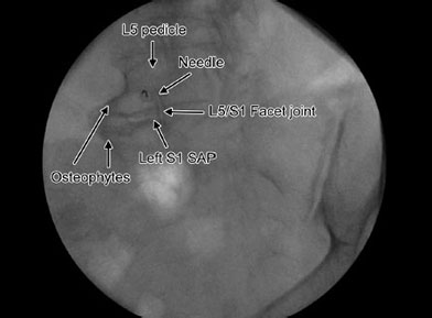
Fig. 6: Fluoroscopy: Knowing the depth of the different spinal structure in relation to the skin entry point of the needle is essential. The image shows vertebral body/disc osteophytes at the left L5/S1 level which produce a shadow in the area of the target for a left L5/S1 transforaminal epidural procedure. However, as we are aware that the vertebral body is anterior to the target point (deeper from skin entry site), we can safely place a curved tip needle over the left L5 pedicle and then navigate below the pedicle and into the intervertebral foramen. (SAP: superior articular process)

Fig. 7: Fluoroscopy—lumbar level: First, obtain a true antero-posterior view in which the spinous process is seen between the two pedicles. Then cephalic or caudal tilt to “square off” the vertebral endplate (the image will appear like the face of an owl). Normally for lower lumbar/upper sacral levels—cephalic tilt; upper lumbar/lower thoracic—caudal tilt; upper thoracic and cervical—depends on patient position. Try both caudal and cephalic tilt and then decide.

Fig. 8: Fluoroscopy—lumbar level: Once the true antero-posterior view is obtained, then rotate the C-arm in the right or the left oblique direction to obtain a “scotty view” as shown in the image. As a general rule, the structures closest to the C-arm move in the direction of the C-arm and the structures away from the C-arm move in the opposite direction.Source: Reproduced with permission from Oxford University Press. Applied anatomy and fluoroscopy for spinal interventions. In Simpson K, Baranidharan G, Gupta S (Eds). Spinal Interventions in Pain Management. 2012; p. 6. [Figure 1.4]

Fig. 9: Fluoroscopy: C-arm—antero-posterior (AP) view: Pillow under the lower abdomen/pelvis to decrease lumbar lordosis. Identify the structure of the lumbar spine. The inset shows the C-arm view from head end. In AP view, the spinous process is in the middle of the two pedicles.

Figs. 10A and B: Fluoroscopy: C-arm—cephalic tilt: C-arm view from the side. The L4/5 and the L5/S1 vertebral end plates are squared showing the disc space at lower lumbar levels; (B) Identify the structures of the spine relevant to the procedure once the AP view is obtained and the vertebral end plates are “squared off” by cephalic or caudal tilt. (IAP: inferior articular process; SAP: superior articular process; TP: transverse process)

Figs. 11A and B: Fluoroscopy: (A) C-arm—caudal tilt: C-arm view from the side; (B) At the upper lumbar and lower thoracic level the C-arm may need to be tilted 5° to 7° caudad to square the vertebral endplates (ignore the RF cannula in this image).

Fig. 12: Fluoroscopy: C-arm in left oblique view: After obtaining the antero-posterior view, the C-arm is tilted cephalic to square the vertebral endplates and then rotated left oblique to obtain a “scotty view.” The inset shows the C-arm view from head end.
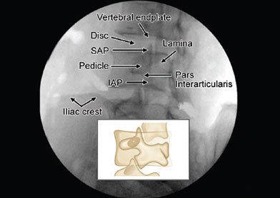
Fig. 13: Fluoroscopy: Left oblique view of the lumbar spine creates the “scotty view.” Identify the structures of the spine before starting the procedure. The area of the junction between the superior articular process (SAP) and the inferior articular process (IAP) is known as pars interarticularis (PI) and a fracture at PI can lead to spondylolisthesis which is more common at the L5/S1 level.

Fig. 14: Fluoroscopy: Identify the junction of the L4 superior articular process (SAP) and the transverse process (TP). Place the needle just below the junction of the left L5 SAP and the TP for medial branch block.

Fig. 15: Identifying two key structures on lumbar fluoroscopy can assist in performing most procedures. Superior articular process (SAP) for: Facet joint injection, medial branch block, medial branch radiofrequency, discogram, disc interventions and infraneural/retrodiscal transforaminal epidural injection. Pedicle for: Selective nerve root block and vertebroplasty. End-on view (gun barrel technique) of spinal needle just infront of the L5 SAP and in the middle of the disc space for L4/5 disc access.Source: Reproduced with permission from Oxford University Press. Applied anatomy and fluoroscopy for spinal interventions. In Simpson K, Baranidharan G, Gupta S (Eds). Spinal Interventions in Pain Management. 2012. p. 6 [Figure 1.4].

Fig. 16: Fluoroscopy: C-arm in right oblique view. After obtaining the antero-posterior view, the C-arm is tilted cephalic to square the vertebral endplates of lower lumbar vertebra and then rotated to the right to obtain a “scotty view.” The inset shows the C-arm view from head end and the side.

Fig. 17: Fluoroscopy: Tip of the needle at the junction of the right superior articular process (SAP) of the S1 vertebra and the ala of the sacrum for L5 dorsal rami (DR) block. If the fluoroscopy C-arm is rotated further oblique, the iliac crest will overshadow the L5 DR target.

Fig. 18: Fluoroscopy: In the lateral view, the vertebral end plates are squared off with the disc space and intervertebral foramen visible. The inset shows the C-arm view from the head end.Source: Gupta S. Stimulation guided pan mapping. In: Baheti DK, Bakshi S, Gupta S, Gehdoo RP (Eds). Interventional Pain Management: A Practical Approach, 2nd edition. New Delhi: Jaypee Brothers Medical Publishers; 2016. pp. 81-3.

Figs. 19A and B: Fluoroscopy: In some patients, it can be difficult to identify/outline the disc space and/or the intervertebral foramen in the lateral view. Moving the C-arm in either direction in the lateral view to “square off”’ the vertebral end plates is commonly known as “wig-wag.” These movements help to identify the disc space and intervertebral foramen at thoracic spine levels and also in some cases at the lumbar and cervical spine levels. The black curved arrows in the image indicate the direction of the C-arm movements.
FLUOROSCOPY FOR PROCEDURES AT THE LUMBOSACRAL AREA
Figures 20 to 43 will show fluoroscopic images of some procedures at the lumbosacral level with the anatomy/bony landmarks identified.

Fig. 20: Fluoroscopy: Targets for left L3 medial branch block (MBB) at the “eye” of the “scotty dog” at L4 level and L4 MBB at L5 level to block the nerve supply to the left L4/5 facet joint.

Figs. 21A and B: Facet joint injection (not commonly performed): Sometimes, the needle can pass through the facet joint and contact the nerve root posteriorly. Lateral view is rarely needed.

Fig. 22: Right oblique view—challenges encountered: Identify the junction of the superior articular process and the transverse process at L4 level. Needle in position for L3 medial branch block (MBB) at L4 level. The target for the left L5 dorsal rami block is obscured by the iliac crest—decreasing the right obliquity of the C-arm will expose the target area for the left L5 DR block. The junction of the SAP and the vertebral endplate can sometimes be mistaken to be the junction of SAP and transverse process.

Fig. 23: Left oblique view for left L4/5 transforaminal epidural injection (subpedicular technique). First, obtain an antero-posterior view followed by cephalic tilt to square the vertebral endplate closest to the target point and then left oblique view to obtain the image shown below (3D principle: Direction, Depth, Direction).Source: Gupta S. Stimulation guided pan mapping. In: Baheti DK, Bakshi S, Gupta S, Gehdoo RP (Eds). Interventional Pain Management: A Practical Approach, 2nd edition. New Delhi: Jaypee Brothers Medical Publishers; 2016. pp. 81-3.

Fig. 24: Lateral view for L4/5 transforaminal epidural injection (subpedicular technique). If there is difficulty in identifying the intervertebral foramen, then moving the fluoroscopy C-arm in a sideward direction in lateral view (wig-wag: see Figure 19) to square the vertebral endplates will improve the view of the intervertebral foramen. (IAP: inferior articular process; SAP: superior articular process).Source: Gupta S. Stimulation guided pan mapping. In: Baheti DK, Bakshi S, Gupta S, Gehdoo RP (Eds). Interventional Pain Management: A Practical Approach, 2nd edition. New Delhi: Jaypee Brothers Medical Publishers; 2016. pp. 81-3.

Fig. 25: Antero-posterior (AP) view—needle with low-volume extension tubing attached in position for left L5/S1 transforaminal epidural injection. Contrast injected under continuous fluoroscopy in AP view. Contrast spread can be seen along the left L5 nerve root, inferior and medial to the pedicle and into the epidural space.

Fig. 26: Procedures at L5/S1 level can be technically difficult. Identify the structures of the lumbar spine relevant to left L5/S1 transforaminal epidural injection. Identify the right sacroliac joint.

Fig. 27: Lateral view with needle tip in the L5/S1 intervertebral foramen. Identify the L4 and L5 pedicles, L4 and L5 vertebral endplates, L4 and L5 vertebral bodies, and L4/5 and L5/S1 intervertebral foramina.

Fig. 28: Contrast injected in AP view under continuous fluoroscopy: What can you see? Would you inject steroid?

Fig. 29: Antero-posterior view of the sacrum: Left S1 foramen. The S2, S3, S4 foramina can also be seen. There are anterior and posterior foramina and they must be overlapped and are often difficult to visualize. Cephalic tilt in an attempt to identify the L5/S1 disc space can facilitate visualizing the S1 foramen. Normally, the S3 foramen is at the level of the lower end of the sacroiliac joint (SIJ).

Fig. 30: Lateral view showing the needle in the epidural space at S1 level. If the disc space/landmarks are not clearly visible, then moving the C-arm in either direction in the lateral position “wig-wag” can square the vertebral endplates defining the bony anatomy better.


Fig. 33: Left oblique view showing the needles in place at the left S1 foramen and at L5/S1 foramen (retrodiscal/infraneural technique) levels. The curved tip needle is just lateral to the lower part of the left S1 superior articular process (SAP). The left iliac crest is overlying the target for L5 dorsal rami.

Fig. 34: Antero-posterior view of the right sacroiliac joint (SIJ). Normally, the medial joint lines are the posterior joint lines (arrows) that can be accessed.3Source: Gupta S, Richardson J. Sacroiliac joint block. In: Baheti DK, Bakshi S, Gupta S, Gehdoo RP (Eds). Interventional Pain Management: A Practical Approach, 1st edition. New Delhi: Jaypee Brothers Medical Publishers; 2009. pp. 198-203.

Fig. 35: The anterior and posterior joint lines of the right sacroiliac joint have been superimposed by contralateral oblique rotation of the C-arm.3Source: Gupta S, Richardson J. Sacroiliac joint block. In: Baheti DK, Bakshi S, Gupta S, Gehdoo RP (Eds). Interventional Pain Management: A Practical Approach, 1st edition. New Delhi: Jaypee Brothers Medical Publishers; 2009. pp. 198-203.

Fig. 36: If the needle is in the sacroiliac joint, then contrast spread can be seen like a thin line along the joint line (arrows).

Fig. 37: Double-needle technique for sacroiliac joint injection [Refer to Chapter 24 (Sacroiliac Joint Block) for more details].

Fig. 38: L5/S1 intervertebral disc access can be challenging as the iliac crest, which is posterior to the disc, can overshadow the target area/skin entry area due to the cephalic tilt and the oblique rotation that is necessary to access the L5/S1 disc space. The artifact is due to suboptimal operating table. (SAP: superior articular process)

Fig. 39: L4/5 disc access—first obtain a true antero-posterior (AP) view with the spinous process in the middle of the two pedicles. Then cephalic tilt to square off the vertebral plate closest to the target area followed by right oblique rotation to obtain the required image. The disc is accessed using the “gun-barrel technique.” The skin entry point is in the middle of the disc space just lateral to the superior articular process. This image determines the Direction of the needle.Source: Reproduced with permission from Oxford University Press. Applied anatomy and fluoroscopy for spinal interventions. In: Simpson K, Baranidharan G, Gupta S (Eds). Spinal Interventions in Pain Management; 2012. p. 6 [Figure 1.4].

Fig. 40: Disc access—the lateral view helps to assess the Depth of the needle and if the tip is in the center of the disc (not close to the vertebral endplates). The image shows needles in place for three-level lower lumbar discogram. If the disc space is not clearly visible, moving the C-arm in either direction (wig-wag) in lateral view can improve disc visibility.Source: Reproduced with permission from Oxford University Press. Applied anatomy and fluoroscopy for spinal interventions. In: Simpson K, Baranidharan G, Gupta S (Eds). Spinal Interventions in Pain Management; 2012. p. 6 [Figure 1.4].

Fig. 41: Right oblique view: The tip of the needle is in the pseudojoint between the abnormal right L5 transverse process and ala of the sacrum over which the patient had pain on palpation. There appears to be an L5/S1 foramen formed due to the changes. To rule out transitional vertebra, count from T12 downward if a plain X-ray of lumbar spine is not available.

FLUOROSCOPY FOR PROCEDURES IN THE CERVICAL SPINE AREA
General Considerations
- Procedures at the cervical level are considered more riskier than at the lumbar levels.
- Before performing procedures at the cervical level, it may be advisable to attend/observe some cervical spine procedures being performed by some colleagues experienced in performing such procedures.
- It is advisable to use a shorter spinal needle, e.g., 5 cm long.
- Cervical procedures can be done in lateral, supine, prone, or rarely sitting position.
- In patients with short neck prone position is better but if sitting position is chosen, this has to be done with the patient sitting on an operating table or a trolley (not on a chair) and one should be prepared to manage a vasovagal episode if this occurs.
- Upper cervical procedures can be done in lateral or supine position and prone position may be considered for lower cervical procedures.
- The head, neck, and chest should be positioned appropriately.
- Fluoroscopic image of C-spine should be obtained to identify the target points before scrubbing for the procedure. If target points are not visible please consider changing the position of the patient e.g. lateral position to prone position.
- Generally, upper cervical procedures are done one side at a time, especially 3rd occipital nerve block.
- Consider the risk of pneumothorax when performing procedures at lower cervical levels.

Fig. 43: C-spine model: Cervical procedures are riskier as many important structures are close to each other in a narrow space.

Figs. 44A and B: Cervical spine: Lateral position viewed from the (A) back and (B) head-end. The neck is supported on a roll of sheets/blankets. Both the shoulders are pulled as low as possible so that the target areas in the lower cervical spine are visible. Both knees are bent toward the abdomen/chest and both hands hold the knees, to increase the visibility of the cervical spine.

Figs. 45A and B: Cervical spine: Supine position—lateral view from the (A) side and (B) head-end of the operating table. The head/neck area is placed on a pillow or folded sheets.

Fig. 46: Lateral view of the cervical spine model with the needle tip showing the target point for C4 medial branch block.
Courtesy: Dr Sherdil Nath, FRCA, Consultant in Pain Medicine, Umeå, Sweden.

Fig. 47: Lateral view: After appropriate oblique rotation of the C-arm to the right or left under continuous fluoroscopy and then tilting the C-arm in cephalic or caudal direction, the right and the left articular pillars are superimposed. The facet joint lines appear crisp with the vertebral bodes and disc spaces outlined. The upper largest spinous process is the C2 level, and this helps in identifying the levels. This image is good to identify the target point for C3 medial branch block (MBB). The C-arm will need to be adjusted again if other level MBB are planned. Target is in the center of the rhomboid formed by the articular pillar as shown at C4 level. The pedicle is normally at the posterosuperior area of the vertebral body. There should be a gap between the spinous process (SP) and the articular pillar (AP) as shown by the horizontal white line at C2 level.4Source: Gupta S, Varma S. Cervical medial branch block. In: Baheti DK, Bakshi S, Gupta S, Gehdoo RP (Eds). Interventional Pain Management: A Practical Approach, 2nd edition. New Delhi: Jaypee Brothers Medical Publishers; 2016. pp. 220-9.

Fig. 48: Lateral view of cervical spine. The right and the left articular pillars (APs) and the facet joint lines are not super-imposed and double shadows (parallax) can be seen. To get the correct image (true lateral view) observe the movement of the vertical lateral margins of the APs with right or left oblique C-arm rotation under continuous fluoroscopy to super-impose them thus eliminating the vertical double shadows. Then tilt the C-arm in the cephalic or caudal direction under continuous fluoroscopy to superimpose the oblique/horizontal margins of the APs (facet joint lines) to eliminate the oblique/horizontal double shadow (parallax). This gives a true lateral view with the right and the left articular pillars superimposed which will decrease the risks of performing cervical medial branch procedures.Source: Gupta S, Varma S. Cervical medial branch block. In: Baheti DK, Bakshi S, Gupta S, Gehdoo RP (Eds). Interventional Pain Management: A Practical Approach, 2nd edition. New Delhi: Jaypee Brothers Medical Publishers; 2016. pp. 220-9.4

Fig. 49: Double shadow (parallax): In this image, there is oblique double shadow (parallax) at the C6/7 level. Tilting the C-arm in the cephalic or caudal direction under continuous fluoroscopy will eliminate the double shadow (parallax). Once the oblique double shadow (parallax) is eliminated, the C-arm may have to be rotated in the right or left oblique direction to eliminate the vertical double shadow (parallax) that may have appeared.5Source: Gupta S, Varma S. Cervical medial branch block. In: Baheti DK, Bakshi S, Gupta S, Gehdoo RP (Eds). Interventional Pain Management: A Practical Approach, 2nd edition. New Delhi: Jaypee Brothers Medical Publishers; 2016. pp. 220-9

Fig. 50: Cervical spine lateral view: Identify the double shadow (parallax).Source: Reproduced with permission from Oxford University Press. Applied anatomy and fluoroscopy for spinal interventions. In: Simpson K, Baranidharan G, Gupta S (Eds). Spinal Interventions in Pain Management. 2012. p. 9 [Figure 1.8].

Fig. 51: Fluoroscopy: Cervical lateral view with double shadow (parallax) eliminated after oblique rotation. Count the vertebral levels from C2 (largest spinous process) downward. The tip of the needle is at the centroid of the C5 articular pillar.Source: Reproduced with permission from Oxford University Press. Applied anatomy and fluoroscopy for spinal interventions. In: Simpson K, Baranidharan G, Gupta S (Eds). Spinal Interventions in Pain Management. 2012. p. 9 [Figure 1.8].

Fig. 52: Lateral view: Needle tip is at the target point for a C5 medial branch block (MBB). Note that there is double shadow (parallax) at the C3 and C4 levels. The horizontal double shadow (parallax) along the C3/4 facet joint line can be eliminated by cephalic or caudal tilt and the vertical double shadow (parallax) at C3 level can be eliminated by right or left oblique rotation before performing C4 and C3 MBB, respectively.4Source: Gupta S, Varma S. Cervical medial branch block. In: Baheti DK, Bakshi S, Gupta S, Gehdoo RP (Eds). Interventional Pain Management: A Practical Approach, 2nd edition. New Delhi: Jaypee Brothers Medical Publishers; 2016. pp. 220-9.

Fig. 53: In some patients, the entire cervical spine can be seen. Appropriate patient position and collimation can enhance the image. Needle tip in place for C5 medial branch block (MBB). The C-arm will need to be tilted to eliminate the oblique/horizontal double shadow (parallax) for C6 MBB.4Source: Gupta S, Varma S. Cervical medial branch block. In: Baheti DK, Bakshi S, Gupta S, Gehdoo RP (Eds). Interventional Pain Management: A Practical Approach, 2nd edition. New Delhi: Jaypee Brothers Medical Publishers; 2016. pp. 220-9.

Fig. 54: (A) Anterior inferior oblique view. Patient in lateral position with the C-arm rotated anteriorly with a caudal tilt; (B) Anterior inferior oblique view. The optimal view is when the opposite pedicles appear in the middle of the vertebral bodies (short arrows) and the intervertebral disc appear well defined.

Fig. 55: Cervical spine: Prone position: Antero-posterior (AP) view. The upper chest is supported on pillows or sheets. Both the shoulders are pulled as low as possible with the upper limbs to the side of the body. The head is supported on a ring or a wedge. For cervical medial branch block, the neck is turned to the opposite side of the target areas, thus moving the jaw away from the target areas. For interlaminar epidural, the neck is kept straight and chin tucked under to eliminate the skin folds in the lower neck area.

Fig. 56: Cervical spine: Prone position: Antero-posterior (AP) view with tilt. (AP: articular pillar; TP: transverse process)

Fig. 57: Cervical spine: An antero-posterior (AP) view. Identify the left C7 transverse process. Is this an optimal image for left C7 medial branch block? (Suboptimal image as the C7 not in the center of the screen).

Fig. 58: Antero-posterior (AP) view showing the needle tip at the junction of C7 superior articular process (SAP) and the transverse process (TP).Source: Reproduced with permission from Oxford University Press. Applied anatomy and fluoroscopy for spinal interventions. In: Simpson K, Baranidharan G, Gupta S (Eds). Spinal Interventions in Pain Management. 2012. p. 9 [Figure 1.8].

Fig. 59: Antero-posterior fluoroscopic image of cervical spine with needle tip in position for left C5, C6, and the first target point for the C7 medial branch block. The junction of the C7 transverse process and superior articular process appears like a “ski boot.”Source: Gupta S, Varma S. Cervical medial branch block. In: Baheti DK, Bakshi S, Gupta S, Gehdoo RP (Eds). Interventional Pain Management: A Practical Approach, 2nd edition. New Delhi: Jaypee Brothers Medical Publishers; 2016. pp. 220-9.

Fig. 60: Antero-posterior view of the cervical spine. The target point for the MBB is the most medial aspect on the waist of the respective articular pillar. This image is appropriate for left C4 medial branch block (MBB). The arrow points to the junction of the superior articular process and the transverse process of C7 which appears like a front of a “ski boot.”Source: Gupta S, Varma S. Cervical medial branch block. In: Baheti DK, Bakshi S, Gupta S, Gehdoo RP (Eds). Interventional Pain Management: A Practical Approach, 2nd edition. New Delhi: Jaypee Brothers Medical Publishers; 2016. pp. 220-9.

Fig. 61: Imaginary line bisecting the C2–3 facet joint line. The upper target point (UTP), middle target point (MTP), and lower target point (LTP) along the bisecting line for the third occipital nerve block are shown by the arrows. The middle target point is at the C2/3 facet joint level along the bisecting line.4Source: Gupta S, Varma S. Cervical medial branch block. In: Baheti DK, Bakshi S, Gupta S, Gehdoo RP (Eds). Interventional Pain Management: A Practical Approach, 2nd edition. New Delhi: Jaypee Brothers Medical Publishers; 2016. pp. 220-9.

Figs. 62A to C: Cervical spine: Lateral view: Needle tip in position for (A) upper, (B) middle, and (C) lower targets for the third occipital nerve block.4Source: Gupta S, Varma S. Cervical medial branch block. In: Baheti DK, Bakshi S, Gupta S, Gehdoo RP (Eds). Interventional Pain Management: A Practical Approach, 2nd edition. New Delhi: Jaypee Brothers Medical Publishers; 2016. pp. 220-9.
FLUOROSCOPY FOR PROCEDURES AT THE THORACIC SPINE AREA
General Considerations
- Procedures at the thoracic level are considered more riskier than at the lumbar level.
- Before performing procedures at the thoracic level, it may be advisable to attend/observe some thoracic spine procedures being performed by some colleagues experienced in performing such procedures.
- Consider the risk of pneumothorax when performing procedures at the thoracic levels.
- It may be challenging to identify bony landmarks in some patients due to the presence of ribs and air shadow of the lungs.

Figs. 63A and B: Thoracic fluoroscopy: Antero-posterior view: C-arm viewed from the (A) side and (B) head end. Upper limbs are placed in front of the head to facilitate lateral view if necessary.


Figs. 66A and B: Thoracic fluoroscopy: C-arm lateral view from the (A) side and the (B) head end. The C-arm may need to be moved in either direction (wig-wag) in lateral view to square the vertebral end plates to make to disc and the intervertebral foramen visible as the ribs and other structures around the spine can overlap making it difficult to define the bony anatomy/landmarks.

Fig. 67: Thoracic fluoroscopy: Antero-posterior (AP) view. The spinous process (SP) is in the middle of the two pedicles with the vertebral end plates (VEPs) “squared off” by tilting the C-arm.

Fig. 68: Thoracic fluoroscopy: Right oblique view. Identify the pedicle at the appropriate level for a transforaminal epidural injection. The arrow points to the “end on” view of the needle when performing a transforaminal epidural injection (Direction of the Needle).

Fig. 69: Thoracic fluoroscopy: Lateral view. The tip of the needle is in the intervertebral foramen. Although the foramen is visible, the disc space is not clear (the disc space is seen better in the Figure 70).

Fig. 70: At the thoracic spine level, it can be difficult to identify the intervertebral foramen in the lateral view due to the ribs and air (lung) shadow. Moving the C-arm side-ward direction in the lateral C-arm position (wig-wag) to square the vertebral end plates (VEPs) to make to disc space crisp improves the view of the intervertebral foramen (IF).
FLUOROSCOPY FOR TRIGEMINAL GANGLION INTERVENTIONS
General Considerations
- Trigeminal ganglion interventions can be riskier than procedures at spinal levels.
- Before performing trigeminal ganglion intervention, it may be advisable to attend/observe some trigeminal ganglion procedures being performed by some colleagues experienced in performing such procedures.
- Consider the risk of injuring extra- or intracranial blood vessels.
- It can be challenging to identify bony landmarks.

Fig. 71: Foramen ovale imaging for trigeminal interventions: Positioning the fluoroscope is of prime importance. Straight posteroanterior (PA) projection is obtained with the petrous ridge seen through the orbit (white arrow).

Fig. 72: Foramen ovale imaging for trigeminal interventions: The fluoroscope is then tilted caudad to see the superior border of petrous ridge projected at the inferior border of the maxillary sinus (white arrows).

Figs. 73A and B: Foramen ovale imaging for trigeminal interventions: Ipsilateral oblique rotation is then performed by 10–25° to visualize the petrous ridge below maxillary sinus (A) and above the jawline (B) [white pointer—petrous ridge, white arrow—foramen ovale (FO)]. Only minimal movement in sagittal plane is required to visualize the FO. This modified submental view is best to visualize FO.

Figs. 74A and B: Foramen ovale imaging for trigeminal interventions. (A) Increased caudal tilt changes the orientation of FO to a circle whereas (B) cephalad tilt makes the foramen flat like a slit. A flatter/elliptical orientation is preferred rather than circular as a coaxially oriented needle would be directed to the floor of middle cranial fossa.
REFERENCES
- Gupta S. Stimulation guided pan mapping. In: Baheti DK, Bakshi S, Gupta S, Gehdoo RP (Eds). Interventional Pain Management: A Practical Approach, 2nd edition. New Delhi: Jaypee Brothers Medical Publishers; 2016. pp. 81–3.
- Gupta S, Dhandapani K. Drugs, equipment and basic principles of spinal interventions. In: Spinal Interventions in Pain Management. Simpson K, Baranidharan G, Gupta S. Oxford University Press; 2012. pp. 1–10.
- Gupta S, Richardson J. Sacroiliac joint block. In: Baheti DK, Bakshi S, Gupta S, Gehdoo RP (Eds). Interventional Pain Management: A Practical Approach, 1st edition. New Delhi: Jaypee Brothers Medical Publishers; 2009. pp. 198–203.
- Gupta S, Varma S. Cervical medial branch block. In: Baheti DK, Bakshi S, Gupta S, Gehdoo RP (Eds). Interventional Pain Management: A Practical Approach, 2nd edition. New Delhi: Jaypee Brothers Medical Publishers; 2016. pp. 220–9.