

Dispensing optics is the science of dispensing eyeglasses and contact lenses based on the prescription of an eye care practitioner. The eye care practitioner prescribes a lens power based upon which the dispensing optician dispenses the correct spectacle lens. Most theories of dispensing optics follow the principles of geometrical optics. The principles of geometrical optics are based on the assumption that light rays always travel in straight lines and in a given direction when they are in free space but change their direction, when they encounter any matter. Laws of reflection and laws of refraction are two main theories of geometrical optics. It also follows some of the principles of wave optics. Wave optics assumes that light travels in waves. Interference, diffraction and polarization are three main principles of wave optics. Interference is the ability of the light wave to interfere with itself. Diffraction is the ability of the light wave to spread after passing through an aperture. Polarization refers to the phenomenon in which waves of light are restricted to a given direction of vibration. Light rays after transmitting through the various ocular structures fall on the retina where the stimuli for vision is formed that produces four types of visual perceptions—light sense, form sense, color sense and sense of contrast. The pathway behind the retina carries the signal to the visual cortex where all information is integrated into one single visual perception.
Optical dispensing is also an art—that teaches how to make the spectacle and sculpt the spectacle frame so that it makes contact 2with patient's face comfortably, looks good and also serves the desired function. The art can be learned and mastered by practice and experience. Sculpting the spectacle frame to fit the patient's face needs skillful hands because both anthropometric and cosmetic demands are to be met. The process of dispensing starts right from selecting a frame to taking measurements and fitting the eyewear on the patient's face. Discovery of truths from the patients and discloser of truths to the patients are also two important building blocks of the art.
Today optical dispensing is considered to be an important part of holistic eye care. The reasons are fairly simple. Even the best refraction may not provide the desired results if the lenses are not dispensed effectively. Lenses are used to maximize the vision and lenses are also used to maintain the vision. This implies that enhancement and maintenance are two important goals of optical dispensing. A rightly selected lens material coupled with appropriate lens design is critical to achieve the desired goals; and this is very important aspect of holistic eye care that also comes within the scope of dispensing optics.

LIGHT
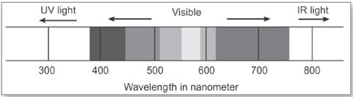
Visible light is a small part of electromagnetic spectrum (Fig. 1.1) ranging from 380 nm to 760 nm that lies between ultraviolet (UV) and infrared (IR) portions with UV rays lying at shorter wavelength end and IR rays lying next to longer wavelength end. Light rays are able to travel through a vacuum or a medium. Light travels very rapidly. In vacuum, the speed of light is 186,282 m/s or nearly 300,000 km/s. Wavelength, frequency and energy describe the properties of light. Wavelength of light is the distance from one peak to the next. It is measured in nanometer or micrometer or angstrom. Our eyes interpret these wavelengths as different colors. If only a limited range of wavelengths enter our eyes, we interpret as certain color. If all wavelengths of visible light enter, we interpret them as white light. If no wavelengths in the visible range are present, we interpret as dark. Human eyes are most sensitive to yellow color which has the wavelength ranging from 570 to 590 nm. Red color is the longest wavelength of light and violet color is the shortest wavelength of light that the human eye can see. Frequency is the number of times per second that a wave vibrates up and down. The longer wavelengths will vibrate fewer times in a given time interval than the shorter ones. Frequency is measured in hertz. Longer wavelength has lower frequency and the shorter wavelength has higher frequency. 3Red color has the lowest frequency. Both wavelength and frequency are of high importance in determining the speed or velocity of light. We can also characterize light by the energy that it carries. Shorter wavelength of light carries intense energy than longer wavelength of light. They carry enough energy with them to damage ocular structure. Classically, the danger of X-rays and gamma rays at the shorter wavelength end is well-known. Shorter wavelength of violet and blue light also spread within the globe and thereby creates veiling effect that affects the sense of contrast.
OPHTHALMIC LENSES
Ophthalmic lenses are transparent bodies that bend light by virtue of the curvature of their surfaces. A surface is formed when a given curve is revolved around a given axis. In case of a spherical lens the surface is formed by rotating a circle about any diameter. A plane surface has zero curvature and may be considered as a spherical surface with infinite radius. A cylinder surface is generated by rotating a straight line about another straight line that is parallel to it. A toric surface is generated by rotating a surface of revolution of a circle around an axis which is outside the circle. Aspheric curves are obtained by rotating a straight line around another line that intersects a conicoid solid, i.e. around axis of symmetry of conicoid solid. The curvature of a surface is given by the angle through which the surface turns in a unit length of arc. The curvature determines how steep or flat the lens surface is. The curvature is specified as inversely proportional to the radius. It implies that the large radius of curvature will have flatter lens surface and smaller radius of curvature will have steeper lens surface.
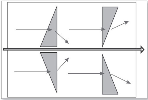
Plus lenses are the combination of prisms base to base while minus lenses are the combination of prisms apex to apex. Understanding spectacle lenses as a combination of prisms is the key to understand how lenses direct light and correct vision. The image viewed through a prism always moves towards the apex, it implies that plus lenses will show “up motion” when it is taken down as the apex of prism lies at the top edge; “towards right” when the lens is taken to left as the apex of prism lies at the right edge and so on. Minus lens will show “down motion” if the lens is taken down as the apex of the prism lies at the center of the lens and so on as shown in Figure 1.2).
Light traveling from air to a prism always bends towards its base. Since a plus lens is the combination of prisms that lies base to base, light rays traveling from air to prism will bend towards its base. It implies that all lights passing through a plus or convex lens will converge to a point as shown in the Figure 1.3). A minus lens is a combination of prism that lies apex to apex. Light rays traveling from air to prism will bend towards its base. It implies that all lights passing through a minus or concave lens will diverge. The optical center of the lens is the singular point through which light rays pass without being deviated.
All ophthalmic lenses have two principal meridians. A meridian is an imaginary line that passes through the optical center of the lens as shown in Figure 1.4). A lens has many meridians, but there are two principal 4meridians those lie perpendicular to each other and meet at the optical center of the lens. The rays of light passing through this meeting point travel undeviated. When these two meridians carry same power, the lens is known as spherical lens and when these two meridians carry different power, the lens is known as sphero-cylinder lens.

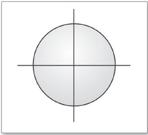
The two principal meridians of an ophthalmic lens are represented diagrammatically in the form of an optical cross that shows the dioptric strength of the lens along the respective meridian. Both the principal meridians are perpendicular to each other as shown in Figure 1.5), e.g. if one principal meridian is at 90°, other would be at 180° and so on. The point at which the two principal meridians meet is known as optical center of the lens. Rays of light passing through this point goes without any deviation as there is no effect of prism at this point. A hypothetical straight line that connects the center of curvature of each lens surface is known as optical axis. The two principal meridians are commonly known as axis meridian and power meridian. Axis meridian has the minimum lens power and power meridian has the maximum lens power as shown in the Table 1.1).

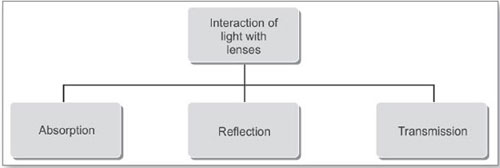
When light travels through a medium it is influenced by the physical, chemical and other properties of the matter. This is called interaction of light. The interactions occur in the form of emission, absorption, transmission and reflection. This interaction determines the appearance of everything we see. Different matters respond to light differently. Transparent matters transmit more light and absorb less whereas translucent matters absorb more light and transmit less. Opaque matters absorb most light. Ophthalmic lenses are transparent bodies and when light interacts with ophthalmic lenses three phenomenon occur as shown in Flowchart 1.1).
Absorption
When the spectrum of the light passes through a medium, it appears to have lost certain wavelength. This is because of light absorption. Selective absorption is the basis for objects having color. A red apple appears as red because it absorbs other colors of the visible spectrum and reflects only red light.
Reflection
Reflection is the redirection of light caused by the light's interaction with matter. The reflected light may have the same or longer wavelength as the incident light, and it may also have a different polarization. When light hits matter, it can be reflected in several ways. Reflection is also known as light scattering.
Transmission
When light interferes with transparent medium, refraction occurs and light is transmitted. Ophthalmic lenses allow us to see because of light transmission through them.
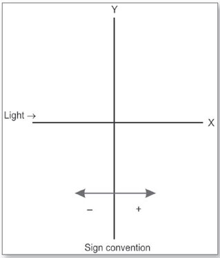
SIGN CONVENTIONS
Sign conventions used to denote ophthalmic lenses is based upon the direction of light. It is being assumed that light always travels from left to right in straight line.
The conventions used are:
- All dimensions are measured from the vertex of the lens to the point in question, or image point.
- Any measurement taken in the course of light is taken as positive and the measurement taken against the course of light is taken as negative.
7Look at the Figure 1.6) in which distance measured to the left of X axis is negative, distance measured to the right of the X axis is positive, distances above the optical axis are positive and distances below the optical axis are negative.

The light rays emanating from an object point and passing through a convex lens has a principal focus in front of the lens and the focal length measured from the lens surface to image point is with the direction of light travel, hence it is taken to be “+”. The light rays emanating from an object point and passing through a concave lens has a principal focus behind the lens and the focal length measured from the lens to image point is against the direction of light travel, hence it is taken to be “—” as shown in Figure 1.7).
POWER SPECIFICATION OF OPHTHALMIC LENSES
Lenses for camera or other optical instruments are always described in terms of focal length and is given by the equation:

Where, | F is focal power of the lens |
FL is the focal length of the lens in meters. |
Ophthalmic lenses, on the hand are described in terms of refracting power. Refracting power is defined as the change in vergence that occurs when light rays passes through a lens. The power of lens describes the extent of change in vergence that happens when the incident wave of light pass through them. Several methods of specifying power of ophthalmic lenses have been used. Some of the common methods are shown in the Flowchart 1.2).
The approximate power of the lens is given by the algebraical summation of front surface power of the lens and the back surface power of the lens (Fig. 1.8). The approximate power of the lens is given by the simple equation:
Fa = F1 + F2
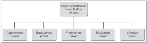

FIGURE 1.8: Front and back surface power as shown by their curves and measured by lens measure watch
Where F1 is the front surface power and F2 is the back surface power as given by the curves of the respective surfaces, measured by lens measure watch. Lens measure watch gives the correct surface power only if it has been calibrated to the respective material index. Lens thickness is not considered in this method. That is why the method gives correct power only when the lens thickness is zero, hence it is called approximate power of lens.
Back Vertex Power
Back vertex power (BVP) is given by the reciprocal of the posterior vertex focal length multiplied by the refractive index of the lens. The following equation defines the BVP of the lens:
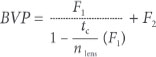
Where
- F1 = Front surface power
- F2 = Back surface power
- tc = Geometrical center thickness
- nlens = Refractive index of lens material.
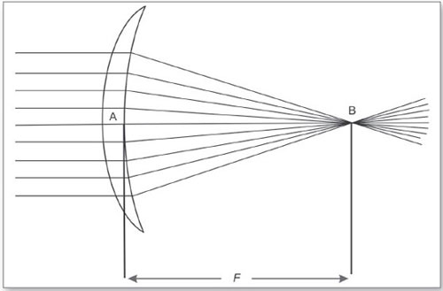
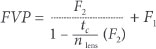
In simple terms BVP can be defined as the ability of a lens to focus parallel rays with reference to its back pole. Figure 1.9) shows light rays from a distance object is focused by a convex lens at its secondary principal focal point B. The distance from the back vertex pole A to the focal point B, is the back 9vertex focal length, given by F. When an ophthalmic lens is ordered from a laboratory, it is denoted in terms of its BVP. The back vertex focal point for each lens falls at the same distance from the eye and coincides with the patient's far point, correcting the refractive error. The instrument used for measuring the back vertex power of a spectacle lens is the focimeter or lensometer. The reading is taken when a lens is placed on the lensometer with its back vertex in contact with the lens rest.
Front Vertex Power
The distance between the front vertex of the lens A to its first principal focus B is called the front vertex focal length of the lens and the reciprocal of the front vertex focal length of the lens is called front vertex power (FVP) of lens (Fig. 1.10). The following equation defines the FVP of the lens:
Where
- F1 = Front surface power
- F2 = Back surface power
- tc = Geometrical center thickness
- nlens = Refractive index of lens material.
Neutralizing measures the FVP of the lens. Two lenses are said to be neutralized, when placed in contact with each other, their total power is zero. If the lens is placed on the lensometer with its front vertex in contact with the lens rest, the recorded lens power will be FVP. FVP is measured for segmented bifocal lenses when fused on the convex surface of the lens.
Equivalent Power
Many optical devices are constructed with a series of lenses separated by air or arranged 10with a series of curve surfaces separated by medium having different refractive indices. In most of this complex system, the center of curvature of all the surfaces fall on a common optical axis. The entire system so devised is imagined to have one single focal point like a thin lens that would produce an image of distant object of the same size and at the same position as produced by the system. The focal length produced by the system is called equivalent focal length and the reciprocal of focal length in meters is defined as the equivalent power of the lens system.
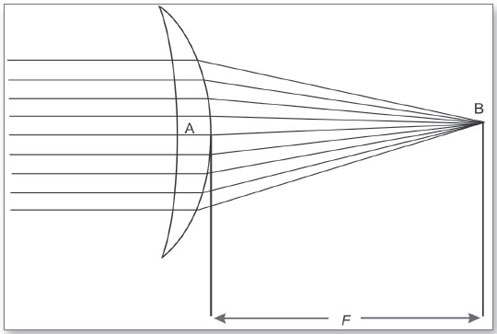
Effective Power
The effective power of the lens may be defined as the ability of the lens to focus parallel rays of light at a given plane. Plus lens is more effective and brings about more changes in vergence as they move farther away from the eyes (Fig. 1.11) and minus lens becomes less effective as they move farther away from the eyes. Two similar types of lenses having similar BVP may have different effective power based upon the vertex distance. It means the effective power of the lens varies with the position of the spectacle frame front on the wearer's face. The lens affectivity formula calculates the effective power of the lens when it is placed at a new distance. The equation is:

Where
- F' = Effective power of the lens at its new distance
- F = Effective power of the lens at its initial distance
- d = Change in vertex distance in meters (d is positive if the vertex distance increases and d is negative if vertex distance decreases)
Example: What is the new effective power of a +10.00 D lens if it is moved in by 5 mm?

= +9.50 Dsph
SYSTEMS OF OPTICAL DISPENSING
Systems of optical dispensing provide measuring procedures that establish a system of reference points to facilitate accurate lens placement into the frame. There are two systems that are very popular as shown in Flowchart 1.3).
Datum System of Optical Dispensing
Datum system is the British standard for spectacle frame measurements. It provides a system of reference points for frames and lenses to facilitate accurate placement of optical center and bifocal segment height. Two horizontal lines tangent to the top and bottom edges of the lenses are drawn that runs parallel to each other (Fig. 1.12). With reference to those two lines various 12lens and frame measuring references can be explained as shown in Flowchart 1.4).


Datum Line
Datum line is the line that lies midway between the horizontal tangents to lens shape at its top and the bottom edges (Fig.1.13). Datum line of the spectacle frame is continuous with the datum line of each lens.
Datum Length
Datum length is the horizontal measure of the lens shape on its datum line.
The midpoint lying on datum line denotes the datum center (Fig. 1.14).
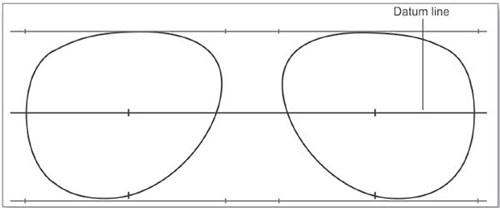
Datum Center Distance
Datum center distance is distance between the datum centers of right and left lenses when the lenses are fitted into the frame.
Distance between Lenses
It is the measure of horizontal distance between the nasal edges of the spectacle lenses along the datum line.

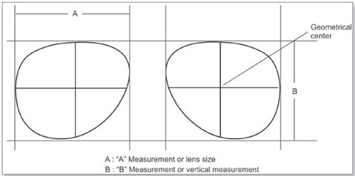
Boxing System of Optical Dispensing
Boxing system is the American standard for spectacle frame measurements. Two vertical lines that are tangent to either side of the lens and run parallel to each other are added, forming a box around the lens as shown in Figure 1.15). With reference to the box so formed important lens and frame measurements as shown in Flowchart 1.5) can be explained.
Geometrical Center
Geometrical center lies at the halfway between the two vertical lines of the box on the datum line. Geometrical center corresponds to the datum center of the British standard. Geometrical center distance (GCD) refers to the distance between the geometric centers of the right and left lens boxes. It can be calculated simply by adding eyewire size to distance between lenses (DBL). It is presumed to be the frame pupillary distance (PD) on the assumption that pupils would correspond to this point. If a frame is marked 52  18, the GCD of the eyewire would be 70 mm.
Size
The size of the lens is given by the length and depth of the box containing the lens. 14This denotes the eye size when talked about spectacle frame and lens size when talked about the lens. Horizontal measure of the box is denoted by “A” measurement under boxing system and vertical measurement is denoted by “B” measurement of the box enclosing the lens. “C” measurement refers to the width of the lens itself along the datum line. While measuring the lens size the measurement begins at the apex of the bevel on one side of the lens to the apex of bevel on the opposite side of the lens. While measuring the eye size the measurement begins at the base of the groove on one side of the eyewire to base of the eyewire on the opposite side of the eyewire. Most frames are marked for their sizes inside of the temple as 54  18. The meaning of such notation under boxing system of measurement is:
- “A” Measurement of the frame is 54 mm.
- Distance between lenses is 18 mm.
- Geometrical center distance between two lenses is 72 mm.

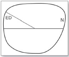
Effective Diameter
The effective diameter is twice the longest radius from the geometric center of a lens to the apex of the lens edge as shown in Figure 1.16). It is found by measuring the distance from the geometrical center of the lens to the apex of the lens bevel farthest from it and multiply it by 2. The measurement 15helps to determine the smallest lens blank from which the lens can be cut. This definition is based on the assumption that the lens optical center will coincide with the geometric center of the frame shape. However, if the lens is decentered towards the nasal direction to match the interpupillary distance of the patient, the longest radius would be measured from the point of optical center to the farthest end of the rim as shown in the Figure 1.17).

Frame Difference
The difference between the horizontal and vertical measurement, measured in millimeter, is known as frame difference. If the frame difference is 0, it implies that the frame eyewire shape is round. If “A” measurement is larger than the “B” measurement, it implies that the frame difference is larger and the shape of the eyewire is rectangular.
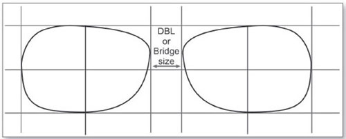
Distance between Lenses
DBL is the measure of distance between the nasal vertical tangents to the lenses at the peak of the bevel. It is measured on the frame as the distance from the inside nasal eyewire groove across the bridge area at the narrowest point (Fig. 1.18). This is usually synonymous with the bridge size if the manufacturer follows boxing system of measurement. If a frame is marked with/18\, it implies that the bridge width of the frame is 18 mm.
Segment Height
Datum line or the lower line of the box enclosing the lens shape is mostly used to specify multifocal segment height. The reference is most commonly given as either distance below or above the datum line, or, distance from the lower line of the box 16enclosing the lens shape. For example, in a frame with “A” measurement 51 mm, “B” measurement 47 mm and the segment top is placed 4 mm below datum line, the segment height would be 19.5 mm from the lower line enclosing the lens.
APPLIED ANTHROPOMETRY AND MORPHOLOGY
The spectacle frames are fitted to match both anthropometric and cosmetic demands. The plane of the spectacle frame ideally makes a parallel relation with eyes so that it neither touches eyebrows nor cheeks. Eyes, nose, eyebrows, cheeks, eyelashes, ears and temporal head—all supported by skull are leading organs that plays important roles in the complicated interaction of the spectacle frame and human face. Familiarity with those organs helps frame measurement, frame selection and frame fitting on the face.
Eyes
The round shape eyeball of approximate diameter of 25 mm is placed within the bony socket of the human skull and is visible through almond shaped palpebral aperture. The overall horizontal width of aperture is around 30 mm. Vertical dimension varies from 10 to 12 mm. Palpebral aperture is slightly inclined to the horizontal meridian. The two eyeballs are placed at the same level in most cases. In cases where they are not at the same level, difference in level rarely exceeds 2 mm. There are certain ocular structures like pupil center, limbus, lower eyelid and canthus that are invariably used as reference for various dispensing measurements.
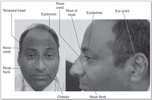
FIGURE 1.19: Facial structures that determine the interaction between spectacle frame and human face
Nose
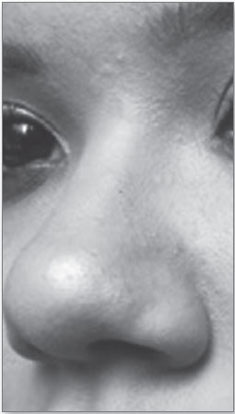
The relation between frame and the nose crest determines whether the spectacle frame fits comfortably or not. Figures 1.19 and 1.20 show the root, crest, flanks and overall 17shape of the nose. They are all important considerations for the comfortable frame fit.
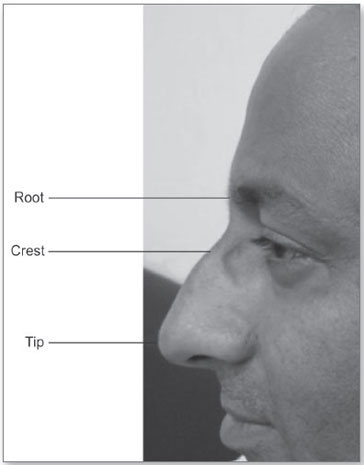
Figure 1.21 shows that the root of the nose is situated at the junction of the nasal and frontal bone and is followed by crest.
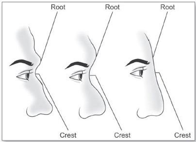
The bridge of the nose is the elevation formed by the nasal bones and is the area where the bridge of the spectacle frame rests on the nose crest (Fig. 1.22). The relative levels of the eyes and the bridge of the nose 18is critical while selecting and fitting the spectacle frame. The protrusion of the nose is measured from a line passing through the apex of the cornea which determines the vertex distance of the spectacle frame front.

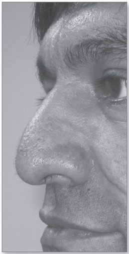
The inclination of nasal flanks, both in horizontal and vertical plane is important while fitting the spectacle frame. In the horizontal plane around the level of lower eyelids, splay angle of the nose pads is measured. These features are unique to an individual patient and are important to fit the spectacle frame properly.
There are different types of nose shapes. Each carries certain unique features that influence the fitting of nose pads of metal frames. Concave nose, straight nose, snub nose and flat nose are four different types that affect the nose pads fitting adjustment differently. The unique features of concave nose are (Fig. 1.23):
- Nose crest is depressed.
- Protrusion of nasal bone is not very significant.
- Inclination of nasal flanks in horizontal plane is relatively more than inclination in vertical plane.
- The tip of the nose is protruded.

The unique features of straight nose are (Fig. 1.24):
- Long and straight nose with no curve or depression is seen at nose crest.
- Protrusion of nasal bone is significant.
- Inclination of nasal flanks in horizontal plane is less than inclination of nasal flanks in vertical plane.
The unique features of snub nose are (Fig. 1.25):
- Small nose relatively depressed nose crest.
- Protrusion of nasal bone is relatively less.
- Inclination of nasal flanks in horizontal plane is more than inclination of nasal flanks in vertical plane.
- The tip of the nose is round and it tends to turn up.

The unique features of flat nose are (Fig. 1.26):
- Small and flat nose crest.
- Protrusion of nasal bone is flat with no protrusion.
- The tip of the nose is flared and wide.
Eyebrows
The shape and position of eyebrows determines the shape of the eyewear that will suit a wearer. An ideal choice is based on the fact that the upper rim of the front of the frame should be either below or in line with the position of the eyebrows.
Cheeks
The position of the cheeks relative to the bridge of the nose determines the inclination of the front of the frame through the angle of sides. A more pronounced cheek is critical to note while adjusting the frame-front for vertical angle. Vertical angle of the frame is adjusted so as to ensure that the lower eyewire does not make any contact with the cheeks.
Eyelashes
The length of the eyelashes of the upper lid determines the minimum vertex distance of the spectacle lens. Ideally eyelashes should never make contact with back surface of the lens.
Ears
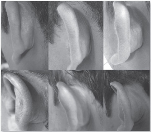
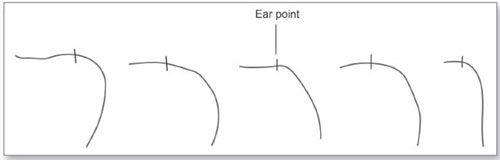
The position of the ears beyond the plane of the nose bridge determines the overall length of the sides of the frame. Their position in the vertical plane also determines the angle of the sides. The ear point lies at the bearing surface of the temple bend. Most ears are set close enough to the head to provide a definite crotch into which the sides can be fitted. They are of great importance to fit the spectacle frame for length to bend, angle of the drop and pantoscopic tilt. Figure 1.27) shows the different shapes of the ear that 21affects the angle of the drop of the temple bend as shown by Figure 1.28).
Temporal Head
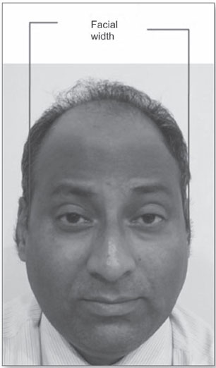
The distance between right and left temporal head of the wearer's head, measured at a level approximately 25–30 mm behind the nose crest plane around the ears (Fig. 1.29) provides facial width which determines the required temple width of the spectacle frame. The measured temple width of the frame has to conform with facial width of the wearer so that the temples when running through the sides of the face makes parallel relation with the temporal bones and makes contact only on top of the ears.
It is important to understand that a number of variations can be seen as far as the shape of human skull is concerned. However, there is one unique aspect that is being observed commonly in most people, i.e. the anterior part of the head is wedge- shaped. The plane of the face normally represents the narrowest that gradually becomes widest around the ear point and is followed by another wedge-shaped part of the skull that points away from the face as shown in Figure 1.30).
PSYCHOLOGY OF DISPENSING
More than 90% of information we receive is through vision. Our vision system is driven by the evolution of visual behavior that enables us to be capable of perceiving 22and then reacting to the environment continuously. Over a period of time a person develops a visual behavior pattern. When the lenses are worn, lot of changes happen in the visual system and the first- time wearer needs to make some changes in his developed visual behavior. The first- time wearer may also feel some unusual sensation. He may feel that the new lenses are “too strong”, or he may notice some changes in depth of perception. Moreover, he may find himself more conscious about the new correction, finding it difficult to coordinate with head and eye movement specially with his new presbyopic correction. A young adult with the small amount of correction may also feel “pulling sensation” which may be associated with the need to establish a new relationship between accommodation and convergence mechanism of the visual system. A young uncorrected hyperope with +2.50 D accommodates by that amount to see at infinity and correspondingly more for near work. If he wears the full correction, he need not accommodate for infinity and has to accommodate less for near work. On the other hand a young uncorrected myope with – 2.50 D can do near work without using any accommodation. If he uses the correction, close work requires accommodation. Accommodation is always associated with convergence. Thus, excess convergence is also relaxed when a hyperope uses correction, whereas correction in myopia stimulates convergence. The straight forward meaning is the person needs to make changes in his visual habits and changes require sustained efforts to overcome the initial difficulties.

When a spectacle lens is worn, a series of changes is noticed in visual performance. Some of these changes are intended and others come along. A notable behavior change is seen in the wearer as plus lens wearer emphasizes more on ground because of expanded space horizon. On the contrary, a minus lens wearer emphasizes more on figure because of constricted space horizon. A plus lens wearer is peripherally more aware, whereas minus lens wearer finds himself good at central detailing. Plus lenses spread light scatter and decrease light intensity and minus lenses decrease light scatter and increase light intensity. This could be a reason, why an optimally corrected hyperope with optimum vision will always find his contrast reduced more than the optimally corrected myope with optimum vision. Some sensitive wearer may feel changes in perception of spatial orientation. While some people are lucky and can see well, for many people adapting to these changes may not come easy. Understanding the elements of change, the 23stages of change and ways to work through each stage may help the wearer to achieve desired goals. No single solution works for everyone, often you need to resort to trial and error method in order to achieve the desired goals. It is during this period, that many people are discouraged and give up. The key to success is to stay motivated and follow the advice of the optician. One of the most important things that the patient needs to do is to give up complaining during the initial period of adaptation and make a sincere try before jumping onto any conclusion.
Getting used to a new prescription or a new multifocal lens requires a patient to break his visual habits of past and develop a new habit that compliments to the new lens type. It means educating the patient is the key for successful adaptation. The better the patient understands what he needs to do, the better are the chances of success. With a new pair of lenses, things may not appear perfect initially, but eventually it has to be perfect. The process of adaptation is similar to breaking into a new pair of shoes. If your spectacle is first ever, the best way to get used to them is to wear them as often as possible or as directed by your optometrist. Using them in small doses unnecessarily delays the adaptation. Adapting to new lenses is normal. By providing a thorough understanding to all parties and patience, the adaptation process can run much smoother for both the patient and practitioner. As a dispensing optician you need to have a working knowledge of applied psychology. Sharing knowledge helps your patients’ understand the condition and maintain the required enthusiasm to adapt to the new lenses.
Moreover, there are barriers to the use of spectacle also. This is obvious when you notice that vision is the most neglected aspect of healthcare. Most people believe that their vision is absolutely perfect until their problem manifests and starts affecting their visual performances. This is because of the adapting ability of the visual system. The visual system does not handicap the process of understanding the environment in which we live. The obvious deficiency in the process of vision slows down gradually until the responses start causing confusion, poor performance and then frustration. If a child performs poor in reading, it is normally taken to be the problem related to his ability. Vision is most often the last thing to blame. Besides, there is a class of people who believe that wearing spectacles creates social barrier, affecting social life and the economic prospects of an individual by restricting the educational and employment opportunities. Girls are particularly vulnerable to social and psychological distress. Even the children had been victimized of negative perception about spectacle. If a child complains of not been able to see the blackboard in the classroom, the grandparents in the family say that he is feigning to wear spectacles. Attitude like this could result in serious problems like psychosocial maladjustments.