

Chapter Outline
- ➲ Definition
- ➲ History of microscopy
- ➲ Simple microscope
- ➲ Compound microscope
- ➲ Parts of microscope
- • Light source
- • Lens
- • Illumination in microscope
- • Condensers
- • Object mechanical stage
- • Objectives
- • Nosepiece
- • Mechanical tube
- • Eyepieces
- ➲ Micrometry
- ➲ Image formation in microscope
- ➲ Specialized microscopy techniques
- • Stereomicroscope
- • Dark field microscope
- • Phase contrast microscope
- • Polarized microscopy
- • Fluorescence microscopy
- • Confocal microscope
- • Electron microscope
- ➲ Maintenance of microscope
The light microscope, now 400 years old, is the standard instrument for the examination of histological preparations. The word microscope is derived from two Greek words micro meaning small and scope meaning to view. Thus, it is an instrument which enables us to view small objects. It magnifies (enlarges) the image of that small object and thus makes it possible to be seen by the viewer.
DEFINITION OF MICROSCOPE
An optical instrument that uses a lens or a combination of lenses to produce magnified images of small objects, especially of objects too small to be seen by the unaided eye.
The early pioneers in the history of the microscope are Digges of England and Hans and Zachcharias Janssen (1590) of Holland, Robert Hooke (1665), John Marshal (1700), Martin Frobenius Ledermüller (1768), Louis Jablot (1755), Meyen (1747). But it was Antony van Leeuwenhoek who was the first to make and use a real microscope (Table 1.1).
Early microscopes were simple microscopes but with advance of science compound microscopes were built.


SIMPLE MICROSCOPE
A simple microscope consists of a single lens or a magnifying glass.
Principle: A lens of short focal length is used to produce an enlarged image of an illuminated object at a short distance; the lens fixed in a frame is adjustable to view the object. The shorter the focal length, the larger the magnified image.
COMPOUND MICROSCOPE (FIGS 1.3A AND B)
A compound microscope consists of two or more lenses.
Principle: If a lens of short focal length is used to produce an enlarged image of an illuminated object at a short distance, then another lens can be so fixed that it would produce a further enlargement of that image.
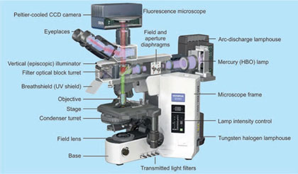
PARTS OF MICROSCOPE
Light Source
The light microscope uses natural daylight or artificial visible light. (The resolution of light microscope is limited by wavelength of its light source). A progression of light sources has developed from oil lamps to the low voltage electric lights of today.
In histopathology laboratories microscopes with three different types of light sources are found, the conventional light microscope using natural or artificial visible light, the fluorescence microscope using ultraviolet light, and electron microscope using a beam of electrons.
Light microscope: Uses a visible light of 400 to 800 nm wavelengths to illuminate an object up to 0.2 μm made visible with perfect optics given in a microscope. In light microscope two different types of illuminations are used.

Fluorescent microscope: Uses ultraviolet light with a shorter wavelength below 400 μm which a light microscope cannot. It can demonstrate, with the help of fluorochrome dyes. High pressure mercury lamp, halogen lamps are used generate ultraviolet light. Light source used in fluorescent microscope is different, i.e. in modern microscope high intensity illumination systems are used. They should to be used with specialized filters for protection of eyes.
Electron microscope: This technique of microscopy is different from light microscopy as it uses a stream of electrons in a magnetic field. This stream of electrons has a very short wavelength (a 50 KV electron beam produces light of 0.0055 nm) This is one hundred thousandth that of the visible light.
Illumination
In light microscope two different types of illuminations are used (Figs 1.4A and B)
Critical illumination: When the object and light source from the substage condenser is in the same plane it is called as the critical illumination, as commonly used in simple equipments, but this produces uneven illumination of the object though modern filament lamps are used.
Kohler illumination: This is used for specialized type of microscopy where an image of the light source is focused by the lamp collector or field lens in the focal plane of the condenser. The image of the field or lamp diaphragm is 4focused in the object plane and the aperture diaphragm is in turn focused at the back focal plane of the objective and can be examined with the eyepiece removed.

Lens
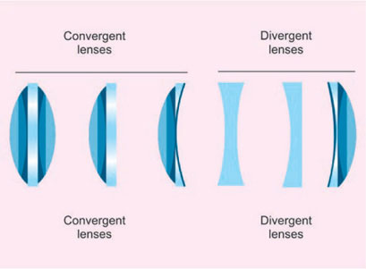
It is named lenses because shaped like the seeds of lentil. Piece of glass or other transparent material, usually circular, having two surface ground or polished in a specific form in order that light ray passing through it either converges or diverges. There are two types of lens which are used. They are (Fig. 1.5):
- Positive: It can be convex shaped and converges rays of light forming real image
- Negative: It is concave shaped and diverge rays and forms virtual image.
Condensers
Light from the lamp is directed into the first major optical component—the sub stage condenser-either directly or from a mirror or prism.
The main purpose of the condenser is to focus or concentrate the available light into the plane of the object, i.e. the condenser collects the maximum possible light reflected by the mirror or the inbuilt light source and condenses or converges it to a very small area at the position of the specimen.
Condensers used for routine microscopy should have the same numerical aperture. The ideal condenser should form a true image of the light source. It is practically useful to have a condenser with a top lens that can be swung out of the path of light, thus filling the whole field with light when very low power objective are used (Fig. 1.6). Three types of condensers are used.
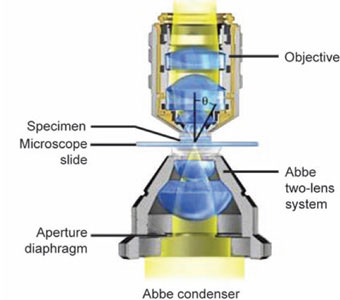
Abbe condenser: Named after Ernst Abbe. It is simplest and least expensive type. Because of its simplicity and good light gathering capacity, it is used with most microscopes unless specified otherwise; it has an NA of 0.25. It consists of two lens elements (Figs 1.7A to C). Abbe condenser is not corrected for spherical and chromatic aberration but serves well for general observation. Some types of Abbe condensers are “variable focus condensers” in which the upper lens element is fixed and lower lens is focusable. When the lower element is raised to it is to position it is similar to the above condenser.
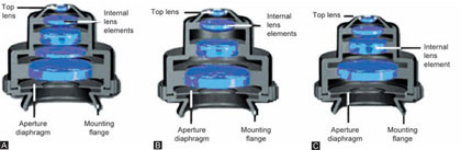
Figures 1.7A and C: Types of condensers used in modern microscopes. (A) Aplantic condenser; (B) Achromatic condenser; (C) Achromat/aplanat condenser
But when its position is lowered, light is focused in between the elements, thus the light can emerge as a large diameter parallel bundle. For 10x the field area is larger. To illuminate this large area the top lens element is removed to achieve the illumination of entire field. For medium and high magnification the top lens element of the variable focus condenser remains in place.
Aplanatic condensers: These types of condensers are optically corrected for spherical aberration. These are not available form all microscope manufacturers, but are of better quality than Abbe condensers (Figs 1.7A to C).
The achromatic condensers: These are corrected for both spherical and chromatic aberrations. It has NA of 1.40. Because of its high degree of correction, it is recommended for research microscopy and for color photomicrography where the highest degree of perfection in the image is desired (Figs 1.7A to C).
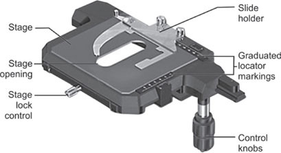
Object Stage
A rigid platform above the condenser which supports the glass slide is object stage. This object stage has an aperture in the center through which the light can pass to illuminate the specimen on the glass slide (Fig. 1.8).
The stage holds the slide firmly and allows the slide movements with a mechanical vertical and horizontal adjustment screws. The mechanical stage is graduated with Vernier scales and the x and y movements assist the operator to return to an exact desired location in the specimen. Traveling range in most of the microscopes is 76 mm(X) 30 mm(Y).
Objectives
Performance of a microscope is dependent wholly on the quality of the optics—the objectives. The main task of objective is to collect maximum light possible from the object, unite it and form a high quality magnified image some distance above.
Every objective has a fixed working distance, focal length, magnification and numerical aperture (NA) (Fig. 1.9).
The working distance is the distance between an object in focus and the front of the lens system.
The focal length is the distance from the center of a simple lens to the point at which parallel rays of light are brought to a sharp focus; in the compound lens it is the distance between an object in focus and a point approximately halfway between the component lenses.

Magnification
It is product of magnification values of eyepiece and objective in a standard microscope.
Magnification in a standard microscope with tube length of 160 mm is calculated using the formula:

For microscopes with tube length other than 160 mm:
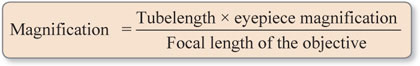
Magnification for low power objective with focal length 16 mm and standard tube length of 160 mm is:

Color Codes
Microscope manufacturers label their objectives with color codes to help in rapid identification of the magnification. In addition to color coding other information is also embossed on the objective (Table 1.2).
Numerical Aperture
The ability of the lens to distinguish fine structural adjacent details in a specimen is known as the resolving power. This ability is expressed in terms of numerical aperture, as NA, as it is usually called.
| |||||||||||||
Numerical aperture depends primarily on the extreme range of the divergent rays that can be made to admit into the lens (angular aperture) and secondarily on the refractive index of the medium between the object and the objective. The relation between numerical aperture, angular aperture and refractive index is

The numerical aperture for any objective is always imprinted on its mount. A 10x achromatic objective usually has a numerical aperture of 0.25 and a 20x achromat will usually have a numerical aperture of 0.50; apochromatic objectives have higher numerical apertures than achromats (Fig. 1.9).
Resolution
It is the smallest distance between two dots or lines that can be seen as separate entities. It depends on the wavelength of light and the NA of the lens. As the NA of the objective increases, the resolving power increases. It is calculated as:
Types of Objectives (Figs 1.10A to C)
In most modern microscopes objectives are usually made up more than one lens. This series of lenses is used to overcome certain limitations in the lenses, i.e.
Optical aberrations: Aberration is the failure of a lens to produce exact point to point correspondence between an object and its image. Every lens system has an aberration to a greater or lesser extent. To improve the image quality, the lenses are designed by combining different lens shapes 7and glass materials.
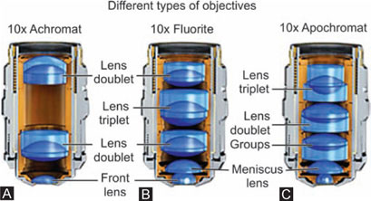
It is possible to construct compound lenses of different glass elements to correct this fault. An achromat lens is corrected for two colors, blue and red, producing a secondary spectrum of yellow/green. This secondary spectrum can be reduced by adding fluorite to objective. Such a lens is called as fluorite lens. Fluorite lenses need to be corrected for yellow green, which is done by adding more lens components. Such type of lens is apochromat which is most expensive.
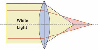
Chromatic aberration: White light is composed of all the spectral colors on passing through a simple lens, each wavelength will be refracted to a different extent, with blue being brought to a shorter focus than red. This defect of lens is ‘chromatic aberration’ and results in an unsharp image with colored fringes (Figs 1.11A and B).
The objective can be both ‘apochromat’ and ‘achromat’ types to correct these optical aberrations.
Spherical aberration: It is caused when light rays entering a curved lens at its periphery which are refracted more than those rays entering the center of the lens and are not brought to a common focus (Fig. 1.12).
Different types of objectives are as followes:
Achromatic: Corrected for two colors red and blue. It is the most widely used for routine purposes.
Fluorite: Green light is brought to a shorter focus and violet light to a longer focus.
Apochromat: All colors are brought into same focus. It is fully corrected for three colors. By the design of the lens and use of fluorite, the formation of a secondary spectrum is almost completely eliminated and all colors are brought to the same focus. These lenses are used especially for photomicrography and for screening cytological smears.

Plan-achromat: Although histological sections are flat the image produced by the microscope is not flat. It is saucer shaped; it is not possible to focus the whole of the field sharply at any one time. This aberration is corrected using flat-field objectives also called plan-achromat lenses.
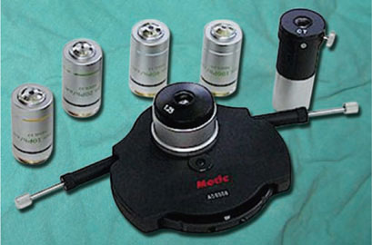
Nosepiece
In most modern microscopes up to six objectives are mounted on resolving nosepiece. For rapid change of all objectives they should be at focus and they should focus the same central area of the section when brought into the position. Such nosepieces are known as ‘par-focal’ and ‘par-central’.
Mechanical Tube
Light from the objective is received into the bottom of the microscope body-tube. From there it travels to the eyepiece 8in a tube called mechanical tube. The distance from objective to eyepiece is called “mechanical tube length” and it is defined as “the distance from the nosepiece opening, where the objective is mounted, to the top edge of the observation tubes where the eyepieces (oculars) are inserted”. In standard microscopes this is 160 mm, while in few special purpose microscopes it is 170 mm.
In most microscopes tube length cannot be altered. Such microscopes are called as finite length microscope. In these microscopes if additional filters such as polarizer, analyzer fluorescent filters are used, tube length becomes more than 160 mm and aberrations will be introduced in the image formed. To overcome this limitation, most of the modern microscopes use infinity corrected optics where image is projected to the infinity. In this system, tube length can be altered without affecting the quality of the image. Infinity-corrected systems have the advantage of being easier to design and also make possible the insertion of less costly accessories in the “parallel” light path. This advanced new optical system allows microscopes to support complex optical component clusters in the optical pathway between the objective and the lens tube. This is especially useful for techniques such as confocal, polarized, DIC, and fluorescence microscopy where specialized lens systems must be employed for optimum results.
Eyepieces
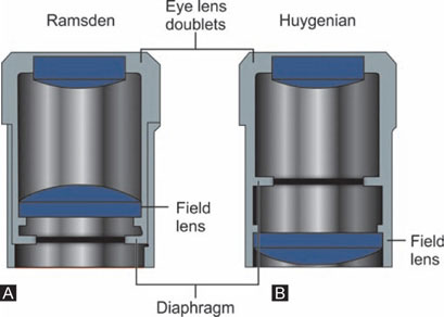
The purpose of an eyepiece in a compound microscope is to enlarge the primary image formed by the objective, and to render it visible as a virtual image in the microscope and also to correct some of the defects of the objective.
Huygenian eyepieces are the simplest form of eyepiece in common use; they are cheap, but they are not corrected for chromatic difference of magnification. Although, Huygenian eyepieces can be used with low-power achromats, they give under-corrected curvature of field and lateral colors with intermediate and higher power objectives. The other main kind of eyepiece is the positive eyepiece with a diaphragm below its lenses, commonly known as the Ramsden eyepiece. These eyepieces are corrected for chromatic aberration of magnification (Figs 1.13A and B).
Different Types of Eyepieces
Compensating eyepieces are compound lenses with a chromatic difference of magnification which is equal and opposite to that of high-power objectives. They are essential for use with apochromatic objectives, but they also improve the performance of most high-power achromatic objectives. Eyepieces for binocular microscopes must be accurately paired, with equal centration, magnification, and field in order to reduce eye strain. Interocular distance should be accurately adjusted, and the microscopist should sit at the correct height for the eyepieces to come to the exact height of the observer's eyes (Fig. 1.14). Eyepieces, generally, are produced with different magnifying powers, ranging from about 4x to 25x. The most common in use are those with a magnifying power of 10x or 15x.

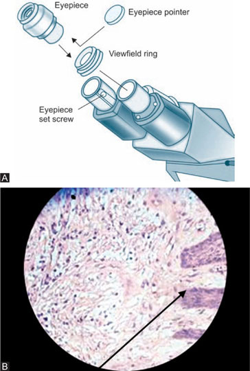
Pointer eyepieces: A fine pointer could be incorporated in the eyepiece in order to enable us to point out a certain portion of the specimen. Such types of eyepieces are called as pointer eyepieces (Figs 1.15A and B).
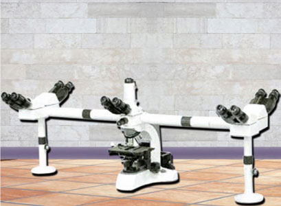
Multihead demonstration eyepieces: Some types of eyepieces are such that 4 to 5 people can view the same portion of an object at a time. This type is called ‘double demonstration eyepieces’ (Fig. 1.16).
Micrometry
The most common method of making such measurements is the use of ocular micrometer and stage micrometer. We can make measurements in compound microscopes only in the range of 0.2 to 25 mm. We cannot measure dimensions smaller than 0.2 mm because it is less than the resolving power of a compound microscope. Likewise, measurement above 25 mm is also not practical because it will be above the average field diameter of a wide field eyepiece. Larger objects can, however, be measured with a stereomicroscope.
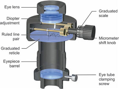
The ocular micrometer (OM) (Fig. 1.17) is a glass disk with a diameter of 1 cm. It is engraved with an arbitrary scale of 100 divisions or less. It is also referred to as a reticle, reticule or graticule. Since it is fitted into the eyepiece of the compound microscope it is more appropriate to call it an ocular micrometer. This is the scale that is used for all measurements. Since the scale is arbitrary, is to be calibrated (standardize) using a known standard scale, the stage micrometer (SM).
A stage micrometer is a standard microscope slide having a scale of defined length. Usually, the scale is 1 mm (1000 μm) divided into 100 divisions, so that one 10stage micrometer division = 10 μm. Such a microlevel scale is made by methods such as photographic process, physical engraving or electro-deposition of a metallic film directly onto the glass surface. A protective cover glass slip is usually mounted on the scale. The scale may be encircled by a black line during use for easy location and focusing under the microscope.
The calibration of the ocular micrometer refers to determination of the distance of one division in terms of the absolute distance of a stage micrometer. A simple Vernier principle is used for this purpose. How many of OM divisions are equal to how many of the SM divisions under a particular microscope–eyepiece–objective combination is found out. Suppose, it is found that 2 OM divisions are equal to 1 SM division which means that 2 OM divisions have a value equivalent to the absolute distance of 1 SM division, i.e. 10 μm. This is given by 1 OM division = 10 μm/2 = 5 μm.
This value is often known as micrometer value or calibration factor. Once this value has been determined, the dimension of any specimen can be calculated by multiplying the number of OM divisions spanned by the specimen with the calibration factor. It must be remembered that a calibration factor only applies to a specific microscope–eyepiece–objective combination (Fig. 1.18).
IMAGE FORMATION IN MICROSCOPE
Real image: The real image in a microscope is formed by the objective lens. The image is formed at a greater magnification, and is inverted. This is when the object is moved nearer the lens.
Virtual image: If the object is placed still nearer the lens within the principal focus, the image is formed on the same side as the object, is enlarged, the right way up, and cannot be projected onto the screen. This is the virtual image. The eyepiece in a microscope forms the virtual image of the real image projected by the objective.
The microscopy utilizes transmitted and reflected light for image formation. Transmitted light is light which passes through the object or specimen from source below and image is create in eyepiece after passing through the objective. Whereas when light reflects from a smooth surface, the incoming light is referred to as an incident light and the light that is bounced away from the surface is termed the reflected light. Reflection of light occurs when the light come upon an object surface that does not absorb the light and bounces the light away from the surface.

The reflection of visible light is a property of the behavior of light that is fundamental in the function of majority of today microscopes. Light is often reflected by one or more plane or flat mirrors within the microscope to direct the light path through lenses that form the virtual images which is visible in the eyepieces. Other optical components in the microscope, such as prisms, filters, and lens coatings, also carry out their functions in forming the image with a crucial dependence on the phenomenon of light reflection.
A transmitted light microscope will typically be of little use to anyone wanting to examine the structure of biological specimen. As a result, the reflected light microscope has been developed for these purposes. Reflected light microscopy is often referred to as incident light, epi-illumination, or metallurgical microscopy (Mostly used in Metallurgy studies), and is the method of choice for fluorescence and for imaging specimens that remain opaque (Fig. 1.19).
In reflected light microscopy, the pathway for reflected light begins with illuminating rays originating in the lamp housing for reflected light. This light next passes through the collector lens and into the vertical illuminator where it is controlled by the aperture and field diaphragms. After passing through the vertical illuminator, the light is 11then reflected by a beamsplitter through the objective to illuminate the specimen.


Light reflected from the surface of the specimen re-enters the objective and passes into the binocular head where it is directed either to the eyepieces or to a port for photomicrography (Fig. 1.20).
The principal focus or focal point is the single point where the parallel rays of light entering the lens are brought together by refraction. The focal point is the point where the clear image of an object is formed. Focal length is the distance between the optical center of the lens and the principal focus.
SPECIALIZED MICROSCOPY TECHNIQUES
Stereomicroscopy (Figs 1.21A and B)
It is optical microscope designed for low magnification observation or a sample using incident light illumination rather than transillumination. It uses two separate optical paths with two objectives and two eyepieces to provide slightly different viewing angles to the left and right eyes.
Stereomicroscopy overlaps macro photography for recording and examining solid samples with complex surface topography where a three-dimensional view is essential for analyzing the detail. The stereo microscope is often used to study the surfaces of solid specimens or to carry out close work such as grossing of specimen, etc.
Dark Field Microscopy
Dark field microscopy is an optical microscopy illumination technique used to enhance the contrast in unstained samples. It works on the principle of illuminating the sample with light that will not be collected by the objective lens, so not form part of the image. This produces the classic appearance of a dark, almost black, background with bright objects on it.
For the dark field method, the cone of light normally illuminating the specimen should not enter the microscope objective, only light that is scattered or reflected by the specimen is seen by the objective. This is achieved in the conventional microscope by use of dark field diaphragm stops or a special dark field substage condenser like Abbe, paraboloid or cardioid condensers. A dark field stop is inserting the stop below the condenser. The light rays from the condenser pass outside the objective and thus form a hollow cone. Now any object with a refractive index different from the surrounding medium, placed within this hollow cone, will only reflect light into the objective and thus the object will appear ‘bright’ against the dark background. The condensers used for this type of microscopy are (Figs 1.22A to C).

Figures 1.21A and B: Stereomicroscope with two objectives and binocular eyepieces. Two light sources reflect light from above the specimen and beneath the object stage for surface topography and viewing low magnification of sections respectively
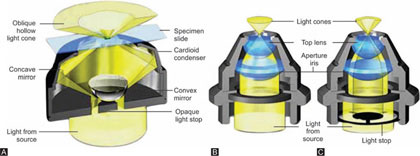
Figures 1.22A to C: Condenser used for dark field microscopy. (A) Cardioid condenser; (B) Abbe condenser; (C) Paraboloid condenser
Two lenses, the objective and eyepiece, are responsible for the formation of the image. The object or specimen is illuminated by the light passing through the condenser which forms the true image of the light source at the specimen plane. The illuminated specimen is magnified by the objective to produce a real, inverted image. A magnified upright virtual image of this real, inverted image is produced by the eyepiece which will be seen by the observer's eyes.
Dark field microscope is used to demonstrate spirochetes trypanosomes, parasites, and other microorganisms in body fluids and cell suspensions, also in flow cell techniques and autoradiographic grain counting. When observed under dark field microscope, these organism appear bright in dark background.
Phase contrast microscopy, first described in 1934 by Dutch physicist Frits Zernike, is a contrast-enhancing optical technique which is utilized to produce high-contrast images of transparent specimens, such as living cells (usually in culture), microorganisms, thin tissue slices, lithographic patterns, fibers, latex dispersions, glass fragments, and subcellular particles (including nuclei and other organelles).
One of the major advantages of phase contrast microscopy is that living cells can be examined in their natural state without previously being killed, fixed, and stained. As a result, the dynamics of ongoing biological processes can be observed and recorded in high contrast with sharp clarity of minute specimen detail.

Phase contrast microscopy is widely employed in diagnosis of tumor cells and the growth, dynamics, and behavior of a wide variety of living cells in culture.
Brightfield microscope can be converted into phase contrast by two specialized accessories. A specially designed annular diaphragm, which is matched in diameter and optically conjugates to an internal phase plate residing in the objective rear focal plane, is placed in the condenser front focal plane.
The phase contrast microscope is probably the most outstanding contribution to microscopy in recent years. It can be used to produce excellent contrast effects, with a wide variety of otherwise transparent specimens. Since it permits visualization of interior details in cell structures, it has a definite advantage over the dark field microscope. Probably its widest application is in the field of tissue culture, where it permits one to examine and photograph living, growing cell.
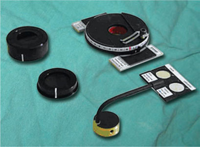
Phase contrast microscope is standard biological microscope and is equiped with modified objective and condensers.
- Condensers: Condenser has a series of annular diaphragm made of opaque glass with a clear narrow ring, to produce a controlled, hollow cone of light.
- Objective: It requires a different size of annulus an image of which is formed by the condenser in the basic focal plane of the objective as a bright ring of light. The Objective has a phase shifting plate or positive phase plate which is a clear glass disk with a circular trough etched in it to half the depth of disk. The trough also contains a neutral density light absorbing material to reduce the brightness of the direct rays which could otherwise obscure the contrast obtained.
The light passing through the trough has a phase difference of 1/4 of wavelength (Figs 1.25A and B).
Principles of Phase Contrast Microscope
The basis of phase contrast microscope is the exaggeration of minute differences in the refractive indices by advancing or retarding light waves, thus converting them into difference of amplitude, which are seen as variation in brightness. Thus if two unstained structures of almost the same refractive index are examined by ordinary illumination it will be found that they are indistinguishable from each other.
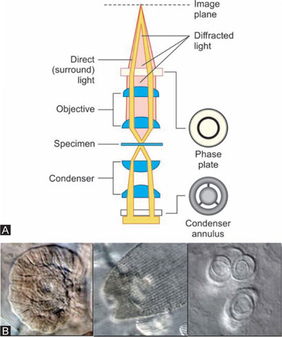
For each transparent or translucent particle in the object, two rays result from an incident light, The direct, or undiffracted ray comes through the angular diaphragm, passes through the object and is focused on the phase shifting ring which either retards or advances the ray 1/4th wavelength with respect to the secondary.
The second ray of the incident beam is modified by being scattered and diffracted in passing around the margin of the object. This ray does not pass through the phase shifting ring but traverses the other areas of the transparent disk, and the wavelength is neither advanced nor retarded.
Thus there is an optical difference of 1/4th wavelength, which causes a phase difference with the asynchronous waves producing reinforced darkness or brightness at certain points. Thus ‘phase contrast’ is made visible to the observer's eye with the help of ‘phase shifting plate’, which enhances the optical effect of the difference.
Applications
Phase contrast microscope is valuable in examination of wet mounts and hanging drop preparations. It can reveal cellular structure of living cell due to difference in the refractive index of the components of the cell and is of great value in cytology, hematology and microbiology (Figs 1.25A and B).
Polarized Light Microscopy (Fig. 1.26)
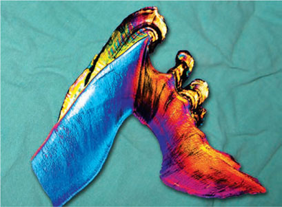
Birefringence is a property, which is shown by crystalline structures, amyloid deposits, proteins, pigments and lipids. When such substances are viewed in a microscope with polarized filters, they may appear bright or even colored against a dark background.
In this type of microscope is used two ‘polarizers’ made up of Nicole Prisms are used. One is placed beneath the substage condenser and is held in a rotatable graduated mount, and can be removed from the light path when not required. The other called ‘analyzer’ is placed between objective and eyepiece and is also graduated for measurements to be taken.
When a birefringent substance is rotated between two polarizers, which are crossed, the image appears and disappears alternately at each 45° of rotation. In a complete revolution of 360° the image appears four times.
Only, the polarizer is used, and if no rotating stage is available, the polarizer itself can be rotated. Changes in intensity and color are seen during rotation. The color changes in a rotation of 90°, and back to its original color in the next 90°. This is due to differential absorption of light, depending upon the vibration direction of two rays in a birefringent substance.
Principle of polarized microscopy: A ray of light consists of electromagnetic waves vibrating in all directions at right 15angles to the path of the ray of light itself. In polarized light the waves are made to vibrate in one plane only. This is achieved by the rotating Nicole prisms, i.e. polarizer and analyzers, which is interrupted in the beam of light.
The specimen are labeled into two categories isotropic or anisotropic.
Isotropic (Singly refractive): The substance which are not illuminated by the change in direction of the beam or 90° rotation of the analyzer, the rays transmitted by the lower prism will not pass through the upper, the field is now dark and the position is called crossed Nicole
Anisotropic (Birefringent or doubly refractive): These substances are seen as positive after the changes in direction of the beam of light, i.e. 90° rotation of analyzer, the objects are seen as bright against a dark background. Collagen fibers, bone matrix, striated muscle, cholesterol, Zenker fixed RBC, pigments such as formalin pigment, crystal such as talc and vegetable, fibers like cotton and linen are anisotropic”.
Applications: The polarizing microscope can be a useful means of identification of tissue components and of exogenous an endogenous crystal specially when combined with special staining techniques and with histochemistry” With this—“The polarizing microscope can be a useful in identification of exogenous an endogenous tissue components and crystal. It is more effective when combined with special staining techniques and histochemistry” (Fig. 1.27).
Objects invisible by ultraviolet light may become brilliantly luminous if coated with a fluorescent substance, like fluorchromes. Fluorchromes are the dyes which absorb radiation (e.g. Ultraviolet light) and become excited; these excited molecules are then capable of emitting radiation of longer wavelength and which disappear almost immediately after withdrawal of the exciting radiation. This is called ‘fluorescence’. Thus fluorescence is the property of some substances, which illuminated by light of certain wavelength causes them to emit the rays of different and longer one. In fluorescence microscopy a fluorescent specimen is illuminated with invisible ‘ultraviolet light’ (UV light has wavelength below 400), the light rays of longer wavelength within the spectrum of visible light are given off and those are seen as various colors of on dark background. A completely dark room is desirable. Brilliant fluorescence depends upon maximum contrast and is reduced if there is background light in the room.
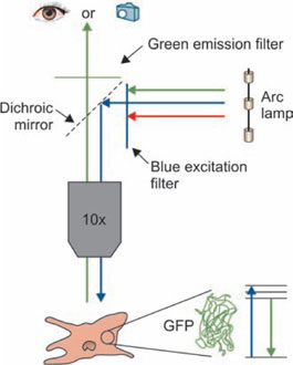
The equipment consists of:
Light source: Halogen lamps which give off sufficient blue light (9400–500 nm). Ultraviolet lamps need to be warmed up before use and have short life.
Filters: Two filters are place, each in between condenser and source (Exciter filter); other is placed between the objective and eyepiece (Barrier filter).
- Exciter filter: The exciter filter is made up of heat filter (heat absorbing filter), red stop filter (this filter removes red light) and wavelength selection (this is main exciter filter that allows only the desired wavelength to pass).
- Barrier filter: Light on passing through these filters illuminates the specimen, the objective collects both exciting and fluorescent wavelengths. The former is removed by barrier filter to prevent short wavelength light from damaging the retina of the eye.
Condensers: Dark ground condensers which do not allow direct light into the objective, and in addition to a dark contrasting background to the fluorescence are used. Routine bright field condensers are able to illuminate the object using all the available energy but they also direct the rays beyond the object into the objective. This is hazardous to the eyes of the observer.
Objectives: For fluorescence microscopy objectives with high numerical apertures are preferred. The intensity increases with increase in the numerical apertures. Hence apochromat are generally preferred.
Eyepiece: The eyepiece with lower magnification is desirable as fluorescence is inversely proportional to the square of the eyepiece magnification.
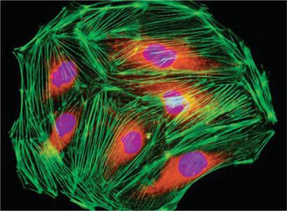
Applications: Fluorescent techniques have become recently widely used in research and fluorchrome dye methods are routinely employed for the demonstration of tissue components, bacteria, fungi, heavy metal in sections and for the identification of malignant cell in exfoliative cytology (Fig. 1.29).
Fluorescent microscopy is the bases for immunofluorescence techniques for the demonstration of antigens and antibodies in tissues and sera.
Fluorochrome dyes which are used routinely are Thioflavin T (amyloid) acridine orange (Malignant cells, mucin and fungi) Auramine-Rhodamine (Acid fast bacilli).
Confocal Microscope (Figs 1.31A and B)
Confocal (“having the same focus”) microscopy is one of the most significant advances in microscopy. The principle of confocal imaging was patented by Marvin Minsky. With this technique it is possible to control depth of field, elimination, reduction of background illumination, to collect serial optical sections from thick specimens and create 3-D image of the the specimen using microcomputers.

In conventional fluorescence entire specimen is illuminated by the light from xenon or mercury bulbs, and light from all areas of the specimen enter the objective and image is obtained. In confocal microscope only a pinpoint area is illuminated and light from this area enters objective and passes through a pinhole filter to eliminate out of focus light. As only a small area is focused very bright light is needed. This is provided by the laser system. Coherent light emitted by the laser system passes through a pinhole aperture that is situated in a conjugate plane (confocal) with a scanning point on the specimen and a second pinhole aperture positioned in front of the detector (a photomultiplier tube). As the laser is reflected by a dichromatic mirror and scanned across the specimen in a defined focal plane, secondary fluorescence emitted from points on the specimen (in the same focal plane) pass back through the dichromatic mirror and are focused as a confocal point at the detector pinhole aperture. The significant amount of fluorescence emission that occurs at points above and below the objective focal plane is not confocal with the pinhole termed.
Out-of-focus light rays and is eliminated. Refocusing the objective in a confocal microscope shifts the excitation and emission points on a specimen to a new plane that becomes confocal with the pinhole apertures of the light source and detector. In this way entire specimen is covered point by point using a scanner, images of individual points are acquired, processed, analyzed and image is displayed.
Applications: The broad range of applications available to laser scanning confocal microscopy includes a wide variety of studies in neuroanatomy and neurophysiology, stem cell research as well as morphological studies of a wide spectrum of cells and tissues. In addition, the growing use of new fluorescent proteins is rapidly expanding the number of original research reports coupling these useful tools to modern microscopic investigations.
Electron Microscope
The electron microscope has gained its fundamental superiority over the light microscope is because of its high resolving power to produce extreme fine details. In light microscopy highest resolution that is possible theoretically is half of the wavelength of light. Thus limit of resolution of light microscopy is 0.2 microns (Fig. 1.32). With use of ultraviolet rays this can be improved to 0.1 microns. But 18intracellular components, certain bacteria and most of the viruses are smaller than this and cannot be visualized.
So attempts were made to use other types of radiation.
In 1933 Ernst Ruska and Max Knoll succeeded in this by building electron microscope. In electron microscope it is possible to enlarge the image 250,000 times or more. This image can be photographed for permanent record and it enlarged 4 to 6 time without undue loss of details, thus giving pictures in the range of two million times as large as the object. Greater resolving power (0.2 nm) makes it possible to obtain images of protein molecular viruses, unstained flagella, internal structure of cell, etc. Two types of electron microscope are used:
- The transmission electron microscope (TEM)
- The scanning electron microscope (SEM).
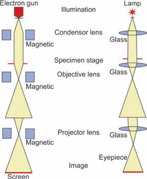
Transmission Electron Microscope
The transmission electron microscope is similar to the light microscope in that it uses lenses to form magnified image. Both have condenser lenses to concentrate the incident beam upon the specimen. This beam passes through the specimen to the objective (magnetic) then to the projector lens and forms an enlarged image onto a fluorescent screen. Difference lies in the radiation used and type of lenses. In electron microscope beam of electron is used instead of visible light, and electromagnetic lenses are used in place of glass lenses (Figs 1.32 to 1.34).
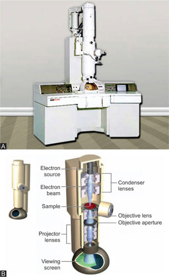
Electron gun: It generates beam of electrons. It is made of anode and tungsten filament, housed in a wehnelt shield. Filament generates electrons by thermionic emission. Between tungsten filament and anode high voltage difference is maintained so that electrons that are emitted from filament are accelerated towards object.
Electron lenses: These electrons pass through a set of electron lenses. These are made up of electromagnetic coils or solenoids. When energized these generate a magnetic field that forces electrons to a focus. Current and voltage in these coils can be varied to change the focus of electron beam.


Image formation: Focused electrons pass through object. These electrons are directed to the viewing screen or image recording unit.
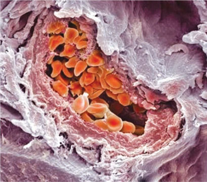
Scanning Electron Microscope
The scanning electron microscope provides a topographic view of the surface contours of the specimen. For this it uses an incident electron beam and the reflected electrons produce the image which is three dimensional. As it mimics our own natural perception, the image is instantly appreciated (Figs 1.35 and 1.36).
MAINTENANCE OF LABORATORY MICROSCOPE
Like every precision mechanical instrument, microscopes will last longer and provide better performance if cleaned and lubricated at regular intervals. The actual work involved is simple and not time-consuming. After long use of the instrument, overhauling, cleaning and lubricating are required. Major defects come from forced movement especially when dried grease or fixed dirt on the movable parts causes wearing out the teeth of the gears. This occurs commonly between fine adjustment and coarse adjustment gears.
Optical Maintenance
After long use of microscope, lenses become covered by fixed dust, dirt and film. Under the worst conditions, such as high humidity, fungi may grow on the inner lens surfaces. This microbial growth may erode the lens surfaces. Such lenses cannot be cleaned routinely and should be returned to the manufacturer.
Optical glasses are generally softer than window glasses so gentle touch is required while cleaning such glasses. Lenses are cemented with adhesive materials. The lenses may become loose, if there is prolonged use of solvent materials are used for cleaning as these dissolve the adhesive cement. So xylene should not be used. Petroleum spirit is recommended by some manufacturers. The recommended 20agent to clean the lenses is xylol. Commercially available detergent based glass cleaning agents may be used. Alcohol and acetone should be avoided as they may seep into the mount and dissolve the cements.
Cleaning of Eyepiece
If eyepieces are observed under good light, dirt and film that may be present on the outer surfaces of lens can be seen readily. Dirt on the inner lens surface may be seen by looking through the field lens. Following steps should be followed for cleaning:
- Loosen dirt with camel-hair brush, and blow it off with blower.
- If oil or other grease film remains, distilled water should be sprayed and wiped off with lens paper or clean lint-free cloth.
- If the film persists lens cleaning solution should be applied and wiped off promptly.
- Circular motion should be applied for cleaning and polishing.
- The necessity of cleaning inner surfaces may be determined by focusing the microscope on a specimen and rotating the eyepiece, if dirt spots rotate, cleaning is required. Unscrew lower and upper lens elements and clean as described for outer surfaces.
Objectives
Objectives should be taken apart from nosepiece for cleaning. Exposed front surfaces of all objectives cleaned. Because the back lens usually located in the deep position though narrow hole, only skilled repairman or the manufacturer can clean it. Usually, lens surfaces of the objectives are smaller than eyepieces, for checking dirt or crack on the surface is recommended to use a magnifying glass.
Condenser
For the Abbe condenser, take apart iris diaphragm unit from condenser, clean the top lens from surface and back surface of the field lens.
BIBLIOGRAPHY
- Clyde Walter Mason, Émile Monnin Chamotl. Handbook of chemical microscopy, Wiley. 1983; 4 (1).
- From cells to proteins. Imaging Nature across dimensions; Valtere Evangelista (Ed). Springer; 2004.
- John Bankroft, Marilyn Gamble; Theory and Practice of histological techniques; Churchil Livingstone; 2008.
- Molecular biology of the cell: Reference edition, Bruce Alberts, (Eds) Garland Science Publishers. 2008: 5 (1).
- Simon Henry Gage. The Microscope and Histology. BiblioBazaar; 2010.
MULTIPLE CHOICE QUESTIONS
- Who discovered microscope:
- Galileo
- Ruska
- Leeuwenhoek
- Janssen
- Range of wavelength used in light microscope is:
- 400–800 nm
- 200–400 nm
- 800–1000 nm
- 40–80 nm
- Range of wavelength used in fluorescent microscope is:
- 600–800 nm
- Below 400 nm
- Below 600 nm
- 400–800 nm
- The numerical aperture (NA) of Abbe condenser is:
- 2.5
- 0.25
- 25
- 0.10
- Traveling range in most of the microscope is:
- 26 mm (X) 30 mm (Y)
- 30 mm (X) 76 mm (Y)
- 96 mm (X) 30 mm (Y)
- 76 mm (X) 30 mm (Y)
- Most expensive lens is:
- Apochromat
- Achromat
- Fluorite
- Plan-achromat
- The numerical aperture (NA) of achromatic condenser is:
- 2.5
- 0.25
- 25
- 1.40
- Length of a mechanical tube in a standard microscope is:
- 100 mm
- 120 mm
- 160 mm
- 200 mm
- Most simple and common form of eyepiece is:
- Huygenian
- Compensating
- Pointer
- None
- Widely used method for diagnosis of tumor cells is:
- Polarized light microscopy
- Fluorescence microscopy
- Phase contrast microscopy
- Confocal microscopy